Read this section before using a result to decide whether to run a program on the machine.
7.1 Reading a result
A result has three parts: the axis-limit warnings (orange), the collision status and its entries (red), and the machined stock in the viewport. A clean result (no orange or red entries, green No collisions found) means: along the path the simulator computed, with the machine, tools, fixture and stock exactly as you described them, no axis left its limits, no modelled tool-side shape (cutter included) came within 0.25 mm of a machine or fixture surface, no shank, holder or machine shape came within 0.25 mm of the material still present, and no rapid or start pose put the cutter more than 0.1 mm into material still present. It does not mean the program is safe. Sections 7.7 to 7.10 (and 7.12 on a GRBL machine) list every known way the result can differ from what the real machine does; the most important are:
- the cutter in the stock on a feed move is never reported, however deep (7.7, item 1);
- the simulated path is only as right as the machine model, the work offsets, the tool lengths and the controller assumptions (7.7, items 14–16, 7.10 and 7.12);
- anything you did not model does not exist for the check.
✓ Measured setup on the setup tag (section 2) only says that you marked every tool and the stock as measured and modelled a fixture. It does not check those numbers, the work zero, the machine model or the controller settings, and it says nothing about the program: a measured setup with a clean result still has every limit listed in this section.
7.2 Axis limits
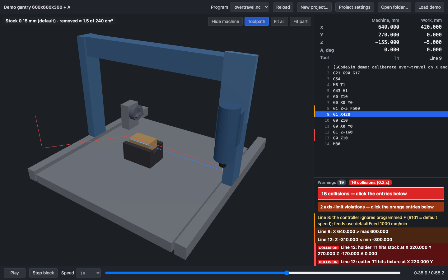
Figure 4. overtravel.nc after clicking Line 9: X 640.000 > max 600.000: the X carriage is 40 mm past its limit; the Do not run verdict counts both violations and the 16 collisions; the travel box of the tool tip is drawn in red; the collision entries are the crash on line 12.
- What is compared: for every segment, the machine coordinate (joint value) of each axis at the segment end, and for arcs also the extreme X/Y/Z values reached inside the arc, against that joint's
limits(tolerance 1e-6 mm). The very first pose (the start pose: all zeros on DDCS,controller.homeon GRBL) is included. Independent-mode dog-leg pieces are checked like any other segment. - Result: an orange warning
X 640.000 > max 600.000(or< min) per axis, direction and segment, at the point where the worst value occurs, taggedAxis limit; theDo not runverdict counts them. It is a warning, not an error: the simulation continues past the limit. - A is checked only if you give its joint
limits; the defaultnullmeans unlimited. - GRBL machines (
dialectgrbl-1.1/grblhal): the warning also says what the controller does, fromcontroller.softLimits(your$20). Withtrue, GRBL checks every target before it moves and stops the job with ALARM:2:X -612.000 < min -600.000 — GRBL stops the job here with ALARM:2 (soft limit); the first such warning of the program adds; the rest of the job does not run on the machine. The simulation still continues, so later warnings show what else would be wrong. Withfalse:X -612.000 < min -600.000 — soft limits are off ($20=0): the carriage runs into its end. On GRBL machine 0 is the homed end, so with limits[-600, 0]aG53 G0 X-10is inside andG53 G0 X10is the warningX 10.000 > max 0.000 — …. DDCS texts have no suffix. - Not compared: where the tool tip, holder or any body is (that is the collision check), the DDCS controller's own soft-limit settings (#234–#243) and whether they are enabled, lines that were skipped, and any motion the controller adds itself (start-up Z lift, M6 move to reference point, G28 to #800–#803).
7.3 Material removal
What is cut. The cutter of the active tool, flat or ball, over its fluteLength only, removes material on every move: feed moves, arcs, rapids, canned-cycle moves, and a tool put in low by a tool change or a length-offset change at the pose where it appears. The shank and the holder never remove material; where they meet material it is a collision (7.4). Moves without a tool in the spindle (T0, or a tool missing from the table) cut nothing. The removal runs in program order in the same pass as the collision check, which uses its result. It shows what the program removes; it is not compared with a target part.
How the stock is modelled. The blank is represented by rays in three directions (along the stock's own x, y and z), resolution apart. Each ray stores the stretches of material along it. Every move is cut as exact swept volumes of the cutter, so along each ray the material ends exactly where the swept cutter surface crosses it (to float precision; leftovers thinner than 0.0001 mm are removed too). Between rays the surface is interpolated.
Accuracy of the cut:
| What | Accuracy |
|---|---|
| Straight moves, 3-axis and indexed (A still, at any angle) | Exact for the modelled cutter, along the rays. |
| Arcs and helices | Within 0.01 mm (cut as chords with a sagitta of at most 0.01 mm). |
| Turning moves (A changes while the stock is on the rotary mount) | Within 0.05 mm: every point of the cutter stays within 0.05 mm of its true path. |
| Features thinner than the resolution (thin walls and ribs, pins, burrs, sharp edges) | May be rounded or lost by up to one resolution. A feature thinner than the resolution in two directions can be missing entirely. |
| The shown cut versus the tool | Lags by up to 2 mm of tool path (the stock is stored in time steps that close every 2 mm of path, at each tool change and at the end). |
The removed volume in the stock status is approximate. It is counted on the z rays, so the blank's volume is the volume on the grid (the demo block is 240.12 cm³ on its 0.15 mm grid instead of 240 cm³) and the removed volume is off by grid aliasing along the outline of each cut. The error is roughly cut perimeter × resolution × depth, with either sign, not a fixed percentage; small and narrow cuts are the least accurate. Measured (bug030): a 6 mm diagonal slot −2.67 % at 0.25 mm and +1.33 % at 0.2 mm; a Ø5 hole −1.64 % at 0.25 mm; pocket.nc +0.51 % at 0.15 mm. The status therefore shows at most three significant digits after ≈.
What the drawing adds. Each ray direction draws its own sheet of the surface; where sheets of two directions meet at a cut edge, closure quads close the gap. What remains: a faint, sometimes broken light hairline along cut edges such as groove rims, up to about 1.4 × the resolution wide, and short skirts, up to 2 × the resolution deep, that are visible when you look along a cut face at a grazing angle. These are drawing artefacts; the model the collision check uses does not contain them. An uncut Ø60×200 cylinder at 0.2 mm is about 2.08 million triangles.
Mesh stock. The blank is filled by casting the rays through the mesh. Triangle orientation is not used: an inside-out closed mesh gives the same material as a correct one. A mesh that is not closed leaves every ray that crosses it an odd number of times empty and gives the orange stock status with Program: stock mesh is not closed: <n> rays crossed it an odd number of times and were left empty; that material is missing for both the drawing and the collision check. A mesh that encloses no volume at all is refused at load (section 4.3).
7.4 Collisions: bodies, rules and order
Bodies on the tool side: the cutter, shank and holder of the active tool (section 4.3), and the collision cylinders and boxes of tool-side links. Bodies on the table side: the meshes of every other link, the fixture mesh and the machined stock as the program has cut it at that moment (7.3): material removed earlier in the same program is gone, material not yet reached is still there.
Every tool-side body is tested against every table-side body, on every kind of move, except the cutter against the stock:
| Tool side \ table side | Table-side links | Fixture | Stock |
|---|---|---|---|
| Cutter | always | always | rapids entering remaining material by more than 0.1 mm, and start poses (7.5); never on feed moves |
| Shank, holder | always | always | always, also on feed moves |
| Tool-side links | always | always | always |
The cutter in the stock on a feed move is cutting, not a collision: it is never reported, however deep, however fast, whether or not the spindle is on.
Order of operations for each move, in program order:
- Start pose. If the move starts at a fresh pose (the first move of the program, the first move after a tool change or a length-offset change, or a move that does not start where the previous one ended), the cutter, shrunk by 0.1 mm, is tested at that pose against the material present. Contact is
cutter T<n> hits stock at …. Then the cutter cuts at that pose. - Rapid dry check. If the move is a rapid (and step 1 found nothing), all its pieces are swept with the shrunk cutter against the material present before the rapid, before any of it is cut. Pieces are at most 0.5 mm long when the rapid comes near the stock; on a turning rapid they are also short enough to keep the cutter within 0.05 mm of its path. The first piece that meets material gives
cutter T<n> hits stock on a rapid move at …, at the end of that piece. - Cut. The move is cut, rapids included.
- Shapes. The move is sampled so that no point of a tool-side body moves more than 0.5 mm relative to a table-side body between two samples (also on arcs and during A rotation at any radius). At every sample, the shank, the holder and the tool-side link shapes are tested against the material left after the move, and every tool-side shape (the cutter included) against the fixture and the table-side link meshes. Every tool-side shape is enlarged by 0.25 mm for these tests.
The spoilboard allowance. A table-side link with spoilboard: a (section 4.2) is the board the stock lies on; a through-cut goes a little into it on purpose. The cutter is tested against a copy of that link's mesh lowered by a along the machine's −Z (the root link's frame), not against the mesh itself; the shank, the holder and the tool-side link shapes are tested against the real mesh. With the 0.25 mm inflation this means: the cutter is reported when its tip goes more than a − 0.25 mm into the board (with 1.5: a cut 1.2 mm deep is clean, 1.3 mm is reported; verified in collision.test.ts), and the entry gives the depth of the deepest tip of that move below the board's top and what the board allows: cutter T1 cuts 1.3 mm into spoilboard (allowance 1.25 mm) at …. A plunge through the whole board is reported, and so is the table under it. The cut into the board is not drawn: material removal stays on the stock. A link without the field is checked as before: on a machine without spoilboard, a profile 0.3 mm into the table is cutter T1 hits base.
A pose after the last motion (a tool change or length-offset change at the end of the program) is checked like a start pose, on the M6 or G43 line, but not cut.
The 0.25 mm inflation (step 4). Consequences:
- Any contact of the modelled shapes at any instant of the simulated path is reported. Thin parts cannot be stepped over.
- A clearance of 0.25 mm or more is never reported.
- A clearance below 0.25 mm can be reported as a collision. Verified on the demo: a holder that stops 0.3 mm short of the vise jaw is clean. A shape that ends a move exactly touching a surface is reported.
- Because shank, holder and links are checked against the material left after the move, a shank or holder that drags through material above the flutes is reported on the feed move that cuts with the cutter below it, and a holder passing through space the cutter cleared earlier is not.
Reporting. One red entry per pair of bodies per run of consecutive segments of one line, at the first touching sample, for example holder T4 hits fixture at X 346.000 Y 289.000 Z -190.000 A 0.000 (machine coordinates of that sample; links are named by their name in machine.json). A later execution of the same line (another subprogram pass) is reported again unless it directly follows the previous one.
When the check does not run. It reports nothing and says so (orange Collision check skipped: …) when the X/Y/Z joint axes are not perpendicular (X, Y and Z joint axes must be perpendicular), when a rotary joint is on the tool-mount branch (rotary joint of link "<name>" is on the tool-mount branch; the material removal is skipped too), or when a prismatic joint sits between the rotary joint and a body it carries (joint "<name>" moves a body carried by rotary joint "<name>" — this joint order is not supported). Motion, limits and playback still work, and in the first and third case the stock is still cut.
7.5 The cutter against the machined stock on rapids and at start poses
The shrunk cutter of steps 1 and 2 above has its radius reduced by 0.1 mm; a flat cutter's bottom is raised by 0.1 mm; a ball keeps its centre. Consequences, verified on the demo:
- A rapid that enters remaining material by more than 0.1 mm is reported; one that enters it by 0.1 mm or less is not. A rapid to 0.08 mm below the top of the demo block is clean, one to 0.12 mm is reported. Along the finished pocket wall, or down to 0.05 mm below the pocket floor, a rapid is clean; 0.2 mm into the wall or below the floor is reported.
- While the stock turns, the allowance is 0.1 ± 0.05 mm, because the turning pieces themselves are only accurate to 0.05 mm. Because all pieces of a rapid are tested against the material present before the rapid (bug027), a turning rapid that passes 0.03 mm or 0.08 mm clear of the stock is clean and one 0.2 mm into it is reported.
- Retracts out of a cut, G98/G99 retracts, G83/G73 re-entries in their own hole, and rapids through a pocket or along a wall cut earlier, by any tool, are clean, because that material is gone. A rapid down a hole narrower than the tool, deeper than the hole, sideways into a wall, or into material that A turned into the path, is reported.
- 0.1 mm is more than the removal can leave behind on a cut surface (arcs 0.01 mm, turning moves 0.05 mm, leftovers 0.0001 mm), so a surface the program cut never causes a report by itself.
- The reported position is the end of the first piece that enters, so it can be up to 0.5 mm past the first contact.
- A cutter of 0.2 mm diameter or less has nothing left after shrinking and is never reported on rapids or at start poses (verified with a Ø0.2 tool rapid 1 mm into the block: clean; Ø0.4: reported).
7.6 When the stock model stops (memory limit)
The stock model is limited to 1 GB. If a program reaches the limit, the removal stops at that line:
- The list gets the red entry
Line <n>: material removal stopped: the stock model reached its 1 GB limit — set a coarser stock.resolution in setup.json, and the stock status turns orange:Stock stopped at line <n> (memory limit) — use a coarser resolution. Everything after line n is shown uncut. - The collision status is never the green
No collisions found: it is the orangeCollision check incomplete: stock model stopped at line <n> (memory limit) — later moves are not checked against the stock, or, with collisions, the red<k> collisions — check incomplete after line <n>. - After line n, rapids and start poses are not checked against the stock at all (verified: a
G0plunge 8 mm into the block after the stop gives no entry). Shank, holder and link shapes are still checked against the stock as it was when the removal stopped, which has more material than the real part, so they can give false alarms. All shapes are still checked against the fixture and the table-side links (verified: thevise.ncholder collision after the stop is still reported). - The stop does not count as lines not executed (7.11): the line ran; only the stock model stopped.
Reaching the limit takes long: the iteration-3 tester's program of 120 facing layers over the whole demo block at 0.1 mm reached it after 128 s, with a 2.5–2.7 GB peak for the browser process. The remedy is a coarser stock.resolution (section 8).
7.7 Every known way a real collision can go unreported
- The cutter on feed moves in the stock is never checked. A wrong work offset, a wrong tool length or a CAM mistake that drives the cutter 30 mm into the stock on G1 is silent as long as only the flute length is in the stock. If the shank or holder enters the stock, that is reported.
- A rapid into material by 0.1 mm or less (0.05–0.15 mm while the stock turns) is not reported (7.5).
- A cutter of 0.2 mm diameter or less is never checked against the stock on rapids or at start poses (7.5).
- Material finer than the resolution. Walls, pins, burrs and edges thinner than the resolution in two directions can be missing from the stock model; a rapid or a shank through them is not reported (7.3).
- Shank against material the same feed move removes. Shank, holder and links are checked against the material left after each move. On a feed move towards the holder side (for example a G1 retract along the tool axis), a shank no wider than the cutter that runs into material which the cutter then removes within the same move is not reported. The rapid dry check (7.4, step 2) catches this case on rapids.
- After a memory stop (7.6), rapids and start poses are not checked against the stock.
- When the stock is not simulated (
Stock not simulated: …), nothing is checked against the stock. If that happens while the collision check itself runs, the collision status can still read the greenNo collisions foundwith the stock caveat; with the real 1 GB limit this can only happen with a mesh stock of extraordinary complexity, and it was reproduced only with an artificially small memory limit (a suspected defect). - The stock is the blank in
setup.jsonas this program cuts it. Real material outside the modelled blank (a larger or differently placed blank, a step, an unmodelled clamp) does not exist for the check. A mesh stock that is not closed has empty rays (7.3). - Table-side bodies are not checked against each other. A long part on the rotary axis swinging into the table, the rails or the tailstock is not reported (verified: a 200 mm tall stock turned through the table gives no entry). The same holds for stock against fixture and fixture against table.
- Tool-side self-collisions (the holder against the spindle housing, a gantry part against another) are not checked.
- Anything not modelled is not checked: tool-side links without
collisionshapes (orange pill), tool-side links with neither mesh nor shapes (no warning), table-side links without a mesh (no warning), clamps, bolts, cables, coolant nozzles, a dust shoe, a probe. - Shapes are approximations: the tool is cylinders (and a sphere for ball tools); tapered or chamfer tools, drill points, bull noses and tapered holders are only as good as the cylinders you enter; STL meshes are only as accurate as you made them. A real part larger than its model can hit where the model does not.
- A body completely inside a machine or fixture mesh without crossing its surface is not detected, because those tests look at surfaces. A move that ends inside such a body is reported when it crosses the surface, but a program that starts with the tool inside one, or a tool change that puts the whole tool inside one, is not. The stock is tested by volume, so anything inside it is found.
- Skipped or ignored lines change the path. Lines with errors, canned cycles in G91 or outside G17, macros, the "line skipped" codes (G31 among them), and ignored codes that move the real machine (G41/G42 compensation, G68 rotation, G15/G16 polar, G90.1/G91.1 arc centres, custom M codes from slib-m.nc) make the simulated path differ from the real one after that line.
- Controller moves that are not in the program are not simulated: the Z lift to safe height at start and resume (#900–#902), the pause lift (#903/#904) on M0, the move to reference point 1 before M6 (#905), and G28 going to #800–#803 instead of machine 0. The first move starts from the start pose in the simulator (machine zero on DDCS,
controller.homeon GRBL); the real machine starts wherever it stands (on GRBL usually where you jogged after homing). - The model must match the machine. Joint value 0 must be the controller's machine 0; the joint directions, the spindle nose height N, the rotary axis position and direction, the work offsets and the tool lengths must be right. The simulator cannot detect a wrong value in any of them; section 5, step 9 has two checks.
- Dynamics are not modelled: acceleration, corner overshoot, following error, backlash, arc linearisation by the controller. Only the commanded path is checked.
- Rotary wrap (#036) is not simulated. With cyclic encoding on, the real A may take a different direction or amount of rotation than the simulated linear A.
- Independent rapids (
rapidMode: "independent") use one speed for all axes,rapidFeed, with A in °/min; real per-axis speeds give a different dog-leg. With the wrongrapidModethe simulated rapid path itself is wrong (dogleg.ncshows the difference). - The check did not run (orange
Collision check skipped: …, 7.4) or failed (Collision check failed: …): nothing is reported. - A cutter in a spoilboard up to its allowance. On a link with
spoilboard(7.4) the cutter may goa − 0.25mm into the mesh unreported, on every move, rapids included, and whether the board is really that thick there or not. The allowance is per machine, not per job: keep it small. - Not checked at all: spindle on/off, spindle direction and speed, feed rate suitability, chip load, coolant.
7.8 Every known false alarm
- Clearances below 0.25 mm between a shank, holder or machine shape and a table-side surface or the remaining material, and a shape that ends a move exactly touching a surface.
- A shank as wide as the cutter in its own cut. When
shankDiameteris not set, the shank is as wide as the cutter. If it follows the cutter into a hole or slot deeper than the flute length, the inflated shank touches the wall the cutter left and is reported (verified: the Ø4 ball mill T3 plunged 20 mm with 16 mm of flutes givesshank T3 hits stock; 15 mm deep is clean). Enter the real neck diameter inshankDiameterwhen it is smaller. - Material that an earlier program removed but the blank in
setup.jsonstill has. - After a memory stop (7.6), shank, holder and links are checked against material that the program has already removed.
- Shapes you made larger than the real parts, and a tool-side box that encloses a table-side part it slides past (every move is then reported).
- A rapid that grazes material by 0.05–0.1 mm while the stock turns can be reported (the allowance there is 0.1 ± 0.05 mm).
Not a false alarm, although it looks like one: the rapid retract of a narrow-neck tool (T-slot, keyseat) whose cutter is under material is reported because the cutter cannot come out through the slot its neck ran in.
7.9 Every known way the displayed part can differ from the real cut
- The real path differs for every reason in 7.7 items 14–19, 7.10 and 7.12: skipped or ignored lines, controller moves, the start from machine zero, the machine model, dynamics, rotary wrap, rapid mode, and every "not confirmed" dialect assumption.
- The A direction is set in
machine.jsonand is not verified on your machine until you run theG0 A90check of section 5, step 7; with the wrong sign every wrapped or indexed feature comes out mirrored. - The real tool: only flat and ball cutters are modelled; drill points, chamfers, bull noses, runout, deflection and flute geometry are not. Material above the flutes is never removed; it is a shank or holder collision instead.
- Resolution: features thinner than the resolution, burrs and sharp edges can be rounded or missing by up to one resolution (7.3).
- Arcs within 0.01 mm and turning moves within 0.05 mm (7.3).
- Drawing artefacts: a faint light hairline up to about 1.4 × the resolution along cut edges, and skirts up to 2 × the resolution visible at grazing angles (7.3).
- Time lag: during playback the shown cut can lag the tool by up to 2 mm of path; while the computation runs, past the computed time the stock is shown as far as computed.
- After a memory stop the rest of the program is shown uncut.
- A mesh stock that is not closed has empty rays where the mesh is open; a mesh stock is drawn tan everywhere, cut faces included.
- The blank is the one in
setup.json; what earlier programs removed is not there unless you modelled it. - The removed volume is approximate (7.3).
- A suggested stock (section 4.5.5, "From program extents") is a guess from the toolpath, not your blank: its size is the cut range plus the cutter radius and a 5 mm margin, Z0 is assumed to be the top when the program cuts below it, and on the rotary work Y0 Z0 is assumed to be on the A axis. Its placement rests it at the fixture's centre without knowing jaws or clamps (task047: in the adjustable vise, against the fixed jaw, with jaws that follow its size — still not your real setup). Enter the real blank's size and position (Measured block) before you trust the cut part or the collisions.
7.10 Controller behaviour assumed but not verified on a real DDCS V4.1
These come from the manuals or from inference, not from your controller. Each can be settled with the test programs in docs/research/03-ddcs-v41-dialect.md §5 (run them in the controller's simulation mode or in air). Every simulated behaviour that depends on one of them carries a warning ending in — behaviour on DDCS not confirmed.
- Canned cycle Z and R as absolute positions (Fanuc); the manuals disagree (test T3). K/L as repeat count (T4). G82 P in ms (T5).
- G28 target: machine 0 versus reference point #800–#803 (T6).
- Which codes the controller rejects (T7); comment,
%,N, lower-case, block-delete handling (T8). - R < 0 arcs (T9), arc radius tolerance 0.002 mm (T10), I/J/K incremental from the start point.
- Helical arcs (the DDCS linearises arcs; forum reports of depth errors on older firmware).
- Rotary feed model
combined(T1). - Rotary wrap behaviour with #036 on (T11).
- M98/M99 with #122, M99 P/L (T12). G41/G42 (T13).
- G53 at feed when G1 is active; axis words without a motion code moving as G0.
- The A direction of your machine. The demo and the example use the negated ISO axis; whether +A turns your chuck the same way is unknown until you run
G0 A90on the machine and in the simulator and compare (section 5, step 7). rapidMode. The defaultinterpolatedis the manual's factory value of #120; your controller's setting is unknown until you read #120. It changes the simulated rapid path.- Rapid speeds. One
rapidFeed(#103) for all axes; in independent mode A is assumed to move at the same number in °/min. Per-axis maximum speeds (#113–#117, #119) and acceleration are not modelled, so the time estimate is short and the independent dog-leg can differ. - That the controller's machine coordinates and H values mean what section 5 assumes.
The same list for GRBL 1.1 and grblHAL machines is section 7.12.
7.11 What the "not executed" count says
The INCOMPLETE banner's N lines were not executed counts each source line the simulation did not execute, once, however many subprogram passes or entries it has:
- lines with an error (unknown codes, parse errors, tool and arc errors, …);
- lines skipped with a warning: G84 and the other
line skippedcodes, macro lines, canned cycles in G91 or outside G17; - every non-empty, non-comment line after the closing
%(listed as one entry on the first of them).
Collisions and the stock model's own entries (a removal stopped at its memory limit, 7.6) do not count: those lines were executed.
A line a GRBL controller rejects (section 6.3) is not executed either, but it does not leave the run INCOMPLETE: the sender stops the job there on the machine, so the banner is DO NOT RUN with N rejected lines (task055).
A word that is ignored on a line that otherwise runs (G41/G42, G93, M7, custom M codes, words after an O label) does not count: the rest of the line was simulated. Its entry stays yellow; read it anyway, because positions after it may differ from the controller.
7.12 Controller behaviour assumed but not verified on a real GRBL controller
The GRBL rules of section 6.3 come from the firmware's source, which is small and public. What is not verified lies outside the firmware: what your sender does, what the vendor's build enables, and your settings. Each item below needs your machine and your sender to settle; the list is the research's §6 (docs/research/05-grbl-dialects.md), items G1–G11, also on the published page GRBL 1.1 and grblHAL in DryRun. Unlike on the DDCS, these do not each carry a warning: the entries that mention one are named.
- G1. The sender stops the job on the first
error:. The simulator assumes it does: a rejected line isDO NOT RUN, and the first one says— the sender stops the job here; the simulation goes on as if you continued. Check: run a file withG81as its third line in your sender, in air; does it stop, pause or skip? - G2. The sender strips
%lines. The simulator gives the note"%" is stripped by senders; GRBL itself rejects it (error:1)and runs on. Check: send a file that starts with%. - G3. M6 pauses for a manual change, and Z is touched off again with the new tool (touch plate, BitSetter, grblHAL's
$341). The simulator does exactly that withtoolChange: "touch-off", and its M6 note says so. gSender's default, Tool Changing: Ignore, does not pause: the machine keeps cutting with the old tool at the old length. Check your sender's tool-change setting. - G4. Machine 0 is the +X +Y +Z end, and the job starts at the homed corner (
controller.home). Check:$H, then?: theMPosshown is the start pose;$23gives the corner and$130–$132the travel (section 5, "The same for a GRBL router"). With the compile optionHOMING_FORCE_SET_ORIGIN, homing sets 0 at the homed corner instead (G7). - G5. The stored G28 position is machine 0 (GRBL's EEPROM default,
controller.g28[0, 0, 0]). If you ever stored another withG28.1, everyG28 G91 Z0goes elsewhere. Check:$#shows[G28:…]. - G6. Soft limits on or off as
controller.softLimitssays. Only the wording of the axis-limit warnings depends on it (section 7.2). Check:$20, and$22(soft limits need homing). - G7. The firmware is stock GRBL 1.1: M7 is rejected,
HOMING_FORCE_SET_ORIGINis off. Check:$I(build info). The X-Controller build enables M7. - G8. A vendor sender's filtering does not change motion. Carbide Motion ignores G54–G59 and G43 and uses its own zero; the simulator does not model that. Check your sender's documentation; on Carbide Motion set the zero there.
- G9. grblHAL builds: canned cycles as LinuxCNC drills them, the G73 retract 1 mm where grblHAL takes
$28(noteG73 retract read as 1 mm; grblHAL uses $28),G43 Honly with a tool table (toolTable). Check:$Iand$$on the controller. - G10. The time estimate: G0 at
rapidFeed, no per-axis$110–$112caps, no$120–$122acceleration, so the real job takes longer. Check: time a job. - G11. A dwell in a Kiri:Moto-style program (
G4 P500 ; dwell for 500ms) is 500 seconds on GRBL, and in the simulator. GRBL's unit is documented; what the post meant is not.