Open the app in Chrome: on the published site the address
/app(Open files or folder… on the home page/); running it yourself,npm install, thennpm run dev, and http://localhost:5173/app. It opens on the Projects window (the home modal, figure 0a) over an empty workspace,Nothing open: nothing is loaded until you open something. From there: New project (the amber card; section 4.5.8), a card of a saved project, Open a folder… (a folder of programs, or a project folder withsetup.json), Open G-code files… (one or more.nc,.ngc,.tap,.gcodefiles), drop files or one folder on the dashed box, or the link Try the demo. Close it (×, Esc or a click outside) to start from the empty workspace: the Project tab says to start by choosing a machine. Open in the header and the DryRun name at its left bring the window back.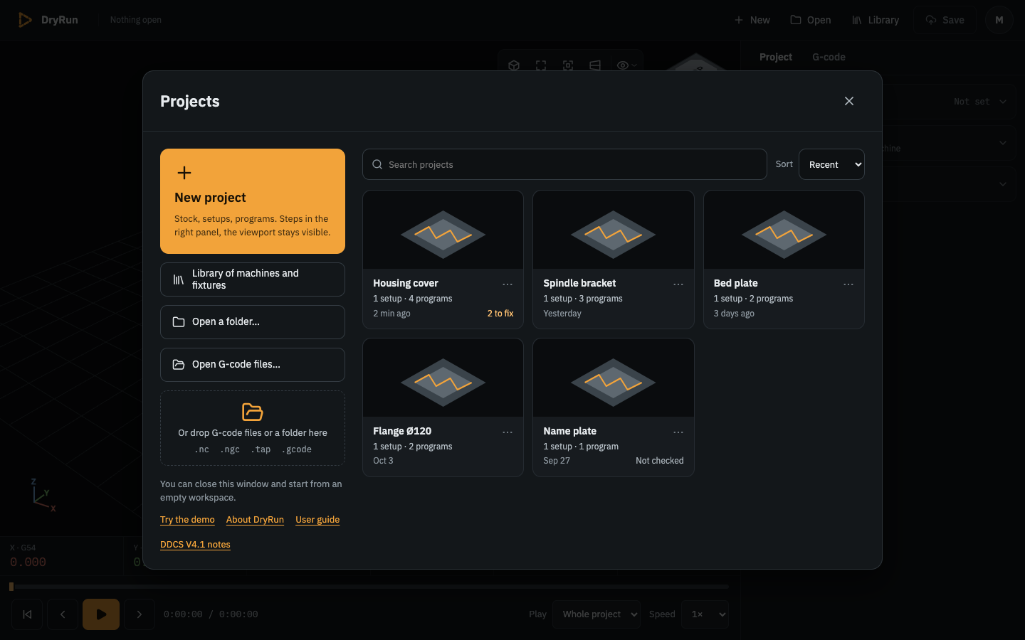
Figure 0a. The Projects window: New project, the library, and the saved projects with their counts, time and status.
Make a project for your own programs (section 4.5.8):
- Click Open → Folder… and pick the folder your CAM post writes its
.ncfiles into (nosetup.jsonneeded). Its programs open in quick view: they run on the default setup (the demo machine, vise and block) under a strip markedQUICK VIEWthat says so. - Click Create a project for these programs → in that strip. The new project opens in the Project tab: its cards with the Setup 1 card open and marked in progress, an amber dot on every item not done yet.
- Open the items one after the other — Machine, Tools, Fixture, the Stock card, the program's item (its work zero). Opening an item fills in its default and those of the items before it: the machine from the catalogue, a placeholder tool for every T number of every program, no fixture, a stock that fits the selected program's cuts (on the table, or in the chuck for a 4-axis program), and the program's zero on that stock. The program marked Main in the Programs step is the one the zero is set with (its tool and G43 H, as you would touch off on the machine); every other program then runs with that same G54.
- Open the Check card and read it (figure 0; opening it first takes every default in one click): the verdict on top says
Not ready — N things to fixorNo problems found; WHAT TO FIX is what is still wrong and which step fixes it — for every program of the folder (each one is interpreted and checked against the axis limits, and a program whose tool and G43 H differ from the main program's says by how much its depth will differ, for exampleb.nc uses G43 H3 with T2: its depth will differ by 10 mm (deeper); collisions and the cut stock only for the selected one, as the summary states); ASSUMED, NOT KNOWN is what was guessed — the tools' placeholder dimensions, the stock, the missing fixture; ZERO FOR THE CONTROLLER is the G54 X … Y … Z … to enter and the tool it is set with; Details lists every assumption in full. The line at the bottom is the selected program's result: errors, warnings, axis limits, collisions. - The project keeps running, not saved (switch to the G-code tab to watch it). Press Save (header, or Cmd/Ctrl+S): the project is kept in this browser among your projects (the Projects window, Open) with the toast
Saved "<name>"; it remembers your program folder, so after the CAM software writes the programs again, Reload shows the new ones. Until you save, the header says Unsaved changes, and reloading or closing the tab asks first. To have the project as files too (a backup, another computer), Export… (the Project tab, under the cards) writessetup.jsonand amachine/folder into a folder you pick — the program folder itself, or another one for a copy. Before relying on it, measure your tools and enter them in the Project tab → Setup 1 → Tools, and check saving once with the checklist in section 4.5.7.
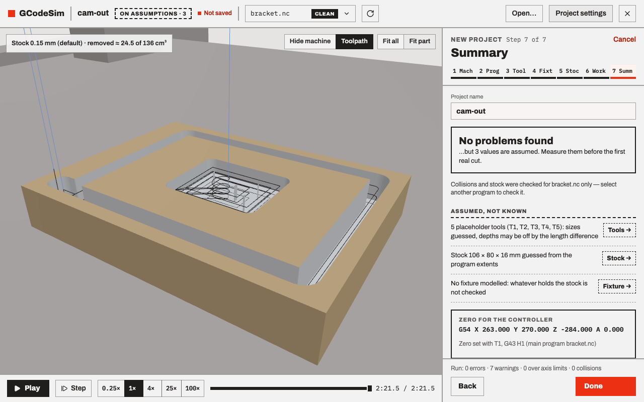
Figure 0. The Check card (the figure shows it as the retired wizard's Summary step) of "Create a project for these programs" for a folder with a Fusion-style bracket program and a drilling program, with every default taken: no problem found, three values assumed (five placeholder tools, a 106 × 80 × 16 stock guessed from the cuts, no fixture), and the G54 values to enter on the controller. The viewport ("Fit part", seeked to the end) shows the pocket and the outer contour cut into the suggested stock.
- Click Open → Folder… and pick the folder your CAM post writes its
To see what results look like, open the demo (the DryRun name, then Try the demo in the Projects window; or the address
/app?demo=demo) and wait until the stock status (the G-code tab, the line under the Problems header) readsStock 0.15 mm (default) · removed ≈ 0 of 240 cm³and the Check tag readsClean. Drag the seek slider to the end: the vise part shows its contour, circle and four drilled holes in bright metal grey on the tan blank (figure 1). The three warnings in the list are normal for this demo (section 3).In the "Program" list of the same demo, look at:
overtravel.nc: an over-travel (verdictDo not run,16 collisions · 2 axis-limit violations,X 640.000 > max 600.000andZ -310.000 < min -300.000), followed by a crash of the cutter, holder and Z head into the stock, the vise and the table (16 red entries).vise.nc: a fixture collision, the holder of T4 hitting the fixed vise jaw on a feed move. Click the red entry: the holder and the vise glow red (figure 2).plunge.nc: a rapid into the stock,cutter T1 hits stock on a rapid move.pocket.nc: a cut pocket 40×20×5 with corner radius 3; clean.slot.nc(a ball slot),dogleg.nc(clean; it shows whyrapidModematters),dialect.nc(codes the simulator flags),rotary.nc(4-axis moves in air).
Open
/app?demo=demo-rotary(a plate and a long block on the rotary axis):jaw.nc: a collision with a rotating machine part, the cutter hitting the chuck while A turns.tailstock.nc: a spindle (tool-side machine link) collision, the Z head hitting the tailstock.wrap.nc: a clean continuous X+A wrap, then an indexed pass at A90.
Open
/app?demo=demo-wrap(a Ø60×200 cylinder in the chuck), seek each program to its end and uncheck Machine under Show ▾ (the eye at the top right of the viewport):index.nc: indexed flats 5 deep at A0 and A90 (3+1 work, A still while cutting).ring.nc: a ring groove 6 wide and 2 deep, cut in one full turn of A.helix.nc: a helix, a ball groove 1.5 deep over three turns of A (figure 3).
Open
/app?demo=demo-grbl(a GRBL router, the Shapeoko 4 XXL, with a sheet on the spoilboard; on the home page, Try the GRBL demo):sign.nc: a clean two-tool Fusion 360 job with M6; the only entry is the note that M6 is simulated as a tool change with Z touched off again.vcarve.nc: a clean one-tool Carbide Create / VCarve file with%and no M6.wrongpost.nc: a Fanuc post's output on GRBL:DO NOT RUNwith4 rejected lines, although nothing collides, because GRBL rejectsO1001,G64,G43 H1andG81(error:20) and the sender stops the job at the first of them (section 3, figure 3a).
Quick view on its own (step 2.1, without creating a project) is a quick dialect check: its programs run on the demo machine and setup, under the
QUICK VIEWstrip that says so (programs whose headers look like GRBL output run on the GRBL demo's Shapeoko 4 XXL instead, and the strip says that is a guess: section 2). This shows at once whether the interpreter understands your post-processor's output: red entries for codes it refuses,tool <n> is not in the setup tool tablefor every tool the demo does not have (that M6 is refused, so the program runs on with the wrong tool; read it as "not simulated", not as a result). Limits, collisions and the cut are those of the demo's 600×600×300 machine, vise and 100×60×40 block, at the demo's G54: they say nothing about your machine or your part. A result is only as good as the setup it runs on, so take everything but the dialect check from your own project (step 2). The DryRun name ends this mode.Read section 7 before you trust any result on your own machine. Its lists 7.7–7.9 are the complete known ways a result can be wrong.
The catalogue has the demo gantry and five GRBL routers (section 4.2); for a GRBL router of your own, section 5 ends with "The same for a GRBL router". Describe your own machine with section 5 and add it to the catalogue (section 4.2): choose the world frame, record the axes on the controller, measure the spindle nose height, the moving parts and the rotary axis, make box-and-cylinder meshes with the script given there, check the A direction with
G0 A90, copy the work offsets and tool lengths, and open the folder with "Open folder…" (or put it undermachines/and choose it in a new project's Machine item). Start with programs in air.