4.1 Project folder and path rules
A project is a folder. Its project file, project.json (format 2: one stock, the setups with their machine, fixture,
placement, tools and programs in order, a zero per work offset; reference and example in docs/project-format.md),
must be directly in it. A folder from before with only a setup.json (format 1, section 4.3) still opens: it is read as
one setup — its programs are the folder's program files, the one setup.json names first — and it runs exactly as it
did; Save and Export… write it as project.json (Export… leaves an old setup.json in the folder alone; project.json
is read first). A project made in the app (New project, or Export… after choosing a catalogue machine) has this layout:
my-part/
  project.json        "machine": "machine/machine.json", the programs in order (the main one first)
  machine/
    machine.json      a copy of the catalogue machine (machines/<id>/ in the repository folder) or of the machine folder chosen
    base.stl  gantry.stl  …   its meshes, as in the catalogue folder
  bracket.nc  drill.nc        the programs (saved into the program folder itself: the files that were there)
  vise.stl  plate.stl         fixture or stock meshes picked in the panel, under their file names
A hand-made project can be laid out as you like within the path rules below. Example (the one used in section 5):
mymill/
  setup.json          the job: which machine, fixture, stock, offsets, tools, program
  machine.json        the machine
  base.stl  tailstock.stl  a_chuck.stl  gantry.stl  x_carriage.stl  z_head.stl
  make-meshes.mjs     optional: the script from section 5 that writes the STL files
  programs/
    wrap.nc
    a90.nc
Path rules (from src/project.ts):
- Paths use
/.setup.jsonpaths (machine,program, fixture and stock meshes) are relative to the project folder. - Link
meshpaths inmachine.jsonare relative to the folder that containsmachine.json. With"machine": "machine/machine.json", a link meshbase.stlmeansmachine/base.stl. ..is allowed as long as the result stays inside the project folder. A path that leaves it is the error<owner>: path outside the project: <path>. To use one machine for several jobs, copymachine.jsonand its STL files into each job folder, or keep one project folder and switch programs.- The program list shows every
.nc,.ngc,.tapand.gcodefile in the folder and its sub-folders (up to three levels deep when opened with "Open folder…").
4.2 machine.json
Top level:
| Field | Type | Required / default | Meaning |
|---|---|---|---|
name |
string, non-empty | required | Shown in the header and in the machine catalogue. |
description |
string | optional | Shown as the tooltip of the machine's card in the catalogue (section 4.5.1). Not used otherwise. |
units |
"mm" |
required | Only millimetres are supported. |
links |
array of links | required, at least one | The parts of the machine (below). Exactly one link has no parent. |
toolMount |
object | required | Where the tool sits (below). |
workMounts |
array of { "name", "link" } |
required, at least one | Named places a fixture or stock can be mounted on. name is any unique non-empty string; link names a link. Typically table → the root link and rotary → the rotary chuck link. |
controller |
object | optional, every field has a default | Controller switches (below). |
Link:
| Field | Type | Required / default | Meaning |
|---|---|---|---|
name |
string, non-empty, unique | required | Used by parent, toolMount.link, workMounts[].link, and in collision messages. |
parent |
link name | omitted or null for the root link only |
The link this one is attached to. Cycles are an error. Order in the file does not matter. |
mesh |
path to an STL file | optional | What the link looks like, in the link's own frame. On a table-side link the mesh is also its collision geometry. On a tool-side link it is only drawn. |
joint |
object | optional; omitted or null = rigidly attached to the parent |
How the link moves (below). |
collision |
array of shapes | optional, default none | Collision shapes, in the link's frame. Allowed only on tool-side links; on any other link it is the error link "<name>": collision shapes are only allowed on the tool-mount branch. |
spoilboard |
number of mm > 0 | optional, default none | The link is a spoilboard: the cutter may go that deep into its mesh without a collision, as a through-cut does on a router (typically 1.5). Allowed only on a table-side link with a mesh; otherwise the error link "<name>": spoilboard needs a mesh on the table side. Any dialect. Section 7.4 has the rule. |
Joint:
| Field | Type | Required / default | Meaning |
|---|---|---|---|
type |
"prismatic" or "revolute" |
required | Slide or rotation. |
letter |
"X", "Y", "Z" or "A" |
required | The program axis that drives it. X, Y, Z must be prismatic and A revolute. Each letter at most once. A machine may omit axes; a program word for a missing axis is an error on that line. There is no B or C. |
axis |
[x, y, z], not all zero |
required | The direction of positive motion (prismatic) or the rotation axis (revolute; positive values turn right-handed about it), in the parent's frame. It is normalised, so [0, 2, 0] is the same as [0, 1, 0]. |
origin |
[x, y, z] mm |
required | Where the link's frame sits in the parent's frame when the joint value is 0. For a revolute joint this is a point on the rotation axis. |
limits |
[min, max] with min < max, or null |
required for prismatic; revolute may be null or omitted (unlimited) |
Allowed joint values (mm or degrees). Must include 0 (error link "<name>": limits must include 0 (the start pose)): a DDCS program starts with all axes at 0, and on GRBL machine 0 is the homed end of the travel. Negative travel is how GRBL counts: a GRBL machine has [−travel, 0] on every axis (below). |
Forward kinematics: world(link) = world(parent) · translate(origin) · move(value), where move is a translation of axis · value or a rotation of value degrees about axis.
Collision shapes (tool-side links only), each array element is exactly one of:
{ "cylinder": { "from": [x, y, z], "to": [x, y, z], "radius": r } }: a flat-ended cylinder fromfromtoto(different points), radius > 0, in the link frame.{ "box": { "min": [x, y, z], "max": [x, y, z] } }: a box aligned with the link frame's axes, min < max on every axis.
A tool-side link with a mesh and no collision is not checked at all; the check says so (link "<name>" has no collision shapes in machine.json and is not checked for collisions) and the pill turns orange. A tool-side link with neither mesh nor shapes is silently not checked.
Tool mount:
| Field | Type | Required / default | Meaning |
|---|---|---|---|
link |
link name | required | The link that carries the spindle (Z head). It decides which links are tool side: the whole branch of the root's child that contains this link. |
origin |
[x, y, z] mm |
[0, 0, 0] |
The spindle nose (gauge line) in that link's frame: the point tool lengths are measured from. |
direction |
[x, y, z], not all zero |
required | Direction from the spindle nose towards the tool tip, normalised. A vertical spindle: [0, 0, -1]. |
Controller switches. Every field is optional; a wrong value is an error naming the field and the allowed values.
| Field | Values | Default | Meaning | DDCS V4.1 parameter |
|---|---|---|---|---|
dialect |
"ddcs-v4.1" / "grbl-1.1" / "grblhal" |
"ddcs-v4.1" |
The controller's G-code dialect: which codes run, warn or are refused (section 6). grbl-1.1: gnea GRBL 1.1 and forks with the same G-code (Grbl-Mega-5X, FluidNC); grblhal: grblHAL (LongMill SuperLongBoard, BlackBox X32, Teensy/STM32 boards), the GRBL 1.1 table plus canned cycles, M6, G43 H with a tool table and more (section 6.3). The other switches depend on it: see "Switches by dialect" below. |
— |
ignoreProgramFeed |
true / false |
true |
true: every F word is ignored (one feed-ignored warning per program) and all feed moves use defaultFeed. false: F is used and is modal; a feed move before any F uses defaultFeed with a no-feed warning. Affects time only. |
#101 "Speed Selection": factory value 1 = use the default speed #102. Check yours. |
defaultFeed |
number > 0, mm/min | 3000 |
Feed used when F is ignored or missing. | #102 (factory 3000) |
rapidFeed |
number > 0, mm/min | 3000 |
Speed of rapid moves (G0, G28, G53 in G0, cycle rapids). In independent mode also the A speed in °/min (an assumption). | #103 "G0 Speed" (factory 3000) |
rapidMode |
"interpolated" / "independent" |
"interpolated" |
interpolated: G0 is a straight line in X, Y, Z, A. independent: every axis runs at rapidFeed and stops on its own, so a G0 becomes a dog-leg of up to four straight pieces. Limits, toolpath, timing and collisions all use the dog-leg. Per-axis rapid speeds are not modelled. |
#120 (factory "Interpolation"). This changes the rapid path; set it to what your controller has. |
rotaryFeedMode |
"combined" / "linear-only" |
"combined" |
How F applies to moves with A. combined: F is the speed along the 4-D length √(ΔX²+ΔY²+ΔZ²+ΔA²) with degrees counted as mm. linear-only: F applies to the XYZ length; a move with only A uses ΔA in °/min. Affects time only. |
No V4.1 parameter; the V4.1 manual's "compound velocity" wording and the V3.1 manual suggest combined. Not verified (test T1 in docs/research/03-ddcs-v41-dialect.md §5). |
rotaryWrap |
true / false |
false |
true only adds the warning rotaryWrap (#036) is not simulated; A is treated as a linear axis in degrees. A is always simulated as a linear axis. |
#036 "A axis cyclic encoding" (factory No) |
dwellPUnits |
"ms" / "s" |
"ms" |
Units of P in G4 P and G82 P. |
No parameter; the V4.1 manual documents G4 P in milliseconds. |
Switches by dialect. A switch that does not belong to the file's dialect is a load error that names it, so a machine converted from DDCS to GRBL says which lines to delete: controller.ignoreProgramFeed is a DDCS V4.1 switch; remove it for grbl-1.1, controller.softLimits is a GRBL switch; remove it for ddcs-v4.1.
| Field | ddcs-v4.1 |
grbl-1.1 |
grblhal |
Values, default and meaning |
|---|---|---|---|---|
rapidFeed, rotaryFeedMode, rotaryWrap |
✓ | ✓ | ✓ | as above |
ignoreProgramFeed, defaultFeed, dwellPUnits, rapidMode |
✓ | refused | refused | GRBL always uses the program's F (a feed move before any F is refused, error:22), reads G4 P in seconds and makes G0 one straight move. |
toolChange |
✓ | ✓ | ✓ | What M6 does and which tool length applies. "pause" (default on DDCS): M6 changes the tool where the machine stands; only G43 H (and on GRBL G43.1 Z) applies a length. "touch-off" (default on GRBL): M6 changes the tool and Z is zeroed again with it, as Carbide Motion, CNCjs, UGS, a BitSetter or grblHAL do: the active tool's length (from setup.json) is always applied, from the program start and after every M6, plus any G43.1 Z, so every tool's tip reaches the same work Z. A G43 H (grblHAL) replaces that length and G49 goes back to it. "controller": M6 goes to the controller raw; GRBL 1.1 refuses it (error:20) and the tool never changes; grblHAL runs it as "pause". |
softLimits |
refused | ✓ | ✓ | true / false, default false: your controller's $20. Only the wording of axis-limit warnings changes (section 7.2): true says GRBL stops the job with ALARM:2, false that the carriage runs into its end. |
home |
refused | ✓ | ✓ | [x, y, z] machine coordinates, default [0, 0, 0]: the start pose of every program, where the machine stands after homing (pull-off included). It must lie inside the joint limits (error controller.home must lie inside the joint limits). |
g28, g30 |
refused | ✓ | ✓ | [x, y, z] machine coordinates, default [0, 0, 0] (GRBL's EEPROM default after $RST=#): the positions stored with G28.1 / G30.1 on your controller ($# shows them as [G28:…] and [G30:…]). G28 / G30 go there (section 6.3). |
toolTable |
refused | refused | ✓ | true / false, default false: whether the grblHAL build has a tool table (N_TOOLS > 0; the SuperLongBoard has 32). false: G43 H is refused (error:20, this grblHAL has no tool table (N_TOOLS = 0)), as are G10 L1/L10/L11. true: G43 Hn applies tool n's length from setup.json (G43 or G43 H0: the active tool's), G10 L1/L10/L11 are accepted with a note (the lengths in setup.json are used), and a T, H or M61 Q that is not a tool in setup.json is error:38. |
GRBL machine space. After homing, GRBL counts machine coordinates from the homed corner: every axis runs from −$13x (the travel) to 0, with 0 at the positive end (back, right, top on most routers). Describe a GRBL machine the same way: limits [−travel, 0] on X, Y and Z, and each joint's origin where the carriage is at that positive end. The readout then shows negative machine coordinates and positive work coordinates, and the G54 values are the ones your controller shows ($#), for example G54 X−420.000 Y−310.000 Z−62.000. Set home to where homing leaves the machine: about [−5, −5, −5] for a back-right homing machine (Shapeoko, X-Carve), about [−travel X + 5, −travel Y + 5, −5] for a front-left one (LongMill, LEAD, 3018). Every program starts there, so the first rapid is drawn and checked from that corner. Example (an 838 × 838 × 102 machine homing back-right):
"controller": { "dialect": "grbl-1.1", "softLimits": true, "home": [-5, -5, -5] }
with the joints' "limits": [-838, 0], [-838, 0] and [-102, 0], and a spoilboard link { "name": "spoilboard", "parent": "base", "mesh": "spoilboard.stl", "spoilboard": 1.5 }.
The machine catalogue. The folder machines/ in the repository folder (next to src/, not under public/) holds one sub-folder per machine: machine.json at its top plus its STL files (sub-folders allowed). The demo gantry is machines/demo-gantry/. To add your machine, drop its folder there, for example machines/my-mill/; no code changes. A running npm run dev notices the new folder and reloads the page (an unsaved draft is lost then), and npm run build includes it. A folder without machine.json at its top is ignored; a machine.json that is not valid JSON is listed under its folder name with the error as its description. Projects never point into the catalogue: choosing a catalogue machine for a project makes it "machine": "machine/machine.json", and saving the project copies the machine into the project's machine/ sub-folder, so a project folder stays self-contained. The catalogue lists the first folder (by name) as the default machine; it stays the demo gantry (the 4-axis 600×600×300 + A, the owner's machine size).
GRBL machines in the catalogue. Five GRBL routers come with DryRun, generated by tools/gen-demo.ts (npm run demo) with the same simple geometry as the demo gantry: a base frame with two rails, a 12 mm spoilboard link (cut allowance 1.5; the table work mount is the spoilboard, so stock rests on it), a gantry (Y) with side plates and a beam, an X carriage, and a Z head whose Ø65 router body and Ø52 spindle nose (the 3018: Ø42) are its collision shapes. The joints run [−travel, 0] (GRBL's machine space, 0 at the back-right-top), controller.home is the homed corner with the pull-off, g28 is [0, 0, 0], toolChange is "touch-off". Z is simplified: at the bottom of Z the spindle nose is 20 mm above the spoilboard. Measure your own Z head before trusting collisions with it.
| Card | Folder | Travel X × Y × Z (mm) | Controller | Start pose (home) |
Soft limits | Source |
|---|---|---|---|---|---|---|
| Genmitsu 3018-PROVer V2 | grbl-3018-prover-v2 |
290 × 180 × 40 | GRBL 1.1 | front-left (−285, −175, −1) | off | sainsmart.com product page. The vendor states neither the homing corner nor $20: front-left (users of the 3018-PROVer) and soft limits off are assumed. |
| Shapeoko 4 XXL | grbl-shapeoko-4-xxl |
838 × 838 × 102 | GRBL 1.1 (Carbide Motion) | back-right (−5, −5, −5) | on | shop.carbide3d.com Shapeoko 4 page; pull-off from the Carbide 3D forum. |
| X-Carve 1000 mm | grbl-x-carve-1000 |
750 × 750 × 65 | GRBL 1.1 (X-Controller) | back-right (−1, −1, −1) | on | all3dp.com review; no vendor page found. Z is disputed: another source gives 114. |
| OpenBuilds LEAD 1010 | grbl-lead-1010 |
730 × 810 × 100 | GRBL 1.1 (BlackBox) | front-left (−725, −805, −5) | on | robotshop.com LEAD 1010 page (29 × 32 × about 4 in). |
| Sienci LongMill MK2 30×30 | grblhal-longmill-mk2-30x30 |
762 × 762 × 125 | grblHAL (SuperLongBoard), toolTable: true |
front-left (−757, −757, −5) | on | resources.sienci.com MK2 specs. X and Y are the nominal 30 in: the exact travel is not published. |
rapidFeed (time estimates only) is a typical $110/$111 of the stock settings: 2000 (3018), 5000 (Shapeoko), 8000 (X-Carve), 4000 (LEAD, LongMill) mm/min; read your own $110–$112. If your machine's $130–$132 differ from the table, copy the folder and change the joint limits. The demo gantry stays the default machine (it sorts first); the Shapeoko 4 XXL is the GRBL demo's machine (section 3). The LongMill runs grblHAL's table with a tool table (toolTable: true): canned cycles, M6, G43 H and M61 run there (section 6.3). The 1.5 mm spoilboard allowance means the cutter may go up to 1.25 mm into the board on any move without a collision entry (1.5 minus the 0.25 mm collision margin); deeper is cutter T1 cuts 1.26 mm into spoilboard (allowance 1.25 mm) with the real depth (section 7.4).
Your own machines. Next to the catalogue, the Library (section 2, Library) keeps machine folders you imported with its Import…. They are kept in this browser (with your projects), not in machines/, so only you see them; clearing the browser's site data removes them (a saved project keeps its own copy in machine/). The Library edits a few fields of such a machine (name, travel, controller and its switches, spoilboard); everything else is described in the folder (this section and section 5) before it is imported.
Not modelled at all: maximum and per-axis speeds (#113–#117, #119), acceleration (#104, #046–#054), the arc speed factor (#112), feed override and whether it applies to G0 (#121), automatic Z lifts at start, resume and pause (#900–#904), the move to reference point 1 before a tool change (#905), the G28 reference point (#800–#803), backlash (#254–#262), the A/B axis selection (#039; only A exists here), slave axes. Soft limits (#234–#243) are not read; you enter limits in joint.limits.
4.3 setup.json
Format 1, before task060: still read and migrated into one setup (section 4.1); the app writes project.json, whose
setups hold the same machine, fixture, tools and stock fields (docs/project-format.md). The fields below are the
same in both, except: the stock's position and rotation are a setup's placement in project.json, the program list
replaces program, and each program's zeros replace workOffsets (an offset on the stock is a rule that follows it,
any other one a point).
Top level:
| Field | Type | Required / default | Meaning |
|---|---|---|---|
machine |
path | required | The machine file, relative to the project folder. |
program |
path | required | The program selected at load. Must exist and have a program extension. |
fixture |
object or null |
optional | One fixture: a mesh (vise, plate, chuck jaws you want checked as a separate body) or, task047, the adjustable machine vise (vise, below). |
stock |
object or null |
optional | One stock: the blank before the program runs. |
workOffsets |
object | optional, default none | Keys G54…G59; each value { "X", "Y", "Z", "A" }, every axis optional and 0 when omitted. A program that selects an offset not listed here runs with a zero offset and the warning <G5x> is not defined in setup.json; using zero offset. |
tools |
array | optional, default none | The tool table (below). |
Fixture and stock placement:
| Field | Type | Required / default | Meaning |
|---|---|---|---|
mount |
work-mount name | required | Which link carries it: on the table it stays still, on the rotary mount it turns with A. |
position |
[x, y, z] mm |
[0, 0, 0] |
Where it sits in the mount link's frame (see the shape for which point). |
rotation |
[rx, ry, rz] degrees |
[0, 0, 0] |
Euler angles, applied as R = Rx·Ry·Rz (three.js Euler order XYZ). |
mesh (fixture) |
path | a fixture has mesh or vise |
STL in the fixture's own frame; placed by position and rotation. |
vise (fixture) |
object | a fixture has mesh or vise |
task047: the adjustable machine vise, generated (below). Both keys at once is the error fixture: give either mesh or vise, not both. |
measured (stock) |
true, or absent |
absent | task041: you measured the real blank (size and placement). Written only when true. Any other value is the error stock: measured must be true or absent. Only the setup tag (section 2) and the panel read it; it changes nothing in the simulation. |
resolution (stock) |
number of mm from 0.01 to 10, or null |
null: chosen from the stock size |
Spacing of the ray grid that models the machined stock (section 7.3). Default: the finest of 0.05, 0.1, 0.15, 0.2, 0.25, 0.3, 0.4, 0.5, 0.75, 1, 1.5, 2 mm that keeps the model within 1 million rays (table in section 8: demo block 0.15 mm, Ø60×200 cylinder 0.2 mm, 300 mm cube 0.75 mm). Finer is slower and uses more memory. A value outside 0.01–10, or not a number, is the error stock: resolution must be a number of mm from 0.01 to 10; a value needing more than 8 million rays is refused at load (below). The status shows the value used and (default) when it was chosen automatically. |
The adjustable vise (task047), for example "fixture": { "vise": { "jawWidth": 100, "jawHeight": 30, "maxOpening": 150 }, "mount": "table", "position": [250, 205, 0], "rotation": [0, 0, 0] }. No file: the app generates three boxes in the fixture's own frame — the bed (60 mm high, jawWidth along x, 2 × 20 + maxOpening along y), the fixed jaw (y 0…20) and the moving jaw (20 mm thick, opening after the fixed jaw), both jaws jawHeight high on the bed. The jaws run along the fixture's x and clamp along its y; position is the corner of the bed under the fixed jaw. The tool, holder and machine are checked against all three, as against a mesh.
| Field | Type | Default | Meaning |
|---|---|---|---|
jawWidth |
mm, 1–1000 | 100 | Width of the jaws (fixture x). |
jawHeight |
mm, 1–1000 | 30 | Height of the jaws above the bed. |
maxOpening |
mm, 1–1000 | 150 | How far the jaws open; the bed is long enough for it. |
opening |
mm from 0 to maxOpening, absent or null |
absent | Absent: the jaws follow the stock: the opening is the stock's size across the jaws (fixture y, the stock turned by its rotation), up to maxOpening, or half of maxOpening without a stock on the vise's mount. A number pins it. |
Any other value is an error such as fixture: vise jawWidth must be a number of mm from 1 to 1000 or fixture: vise opening must be from 0 to maxOpening (150 mm), or absent. The panel writes all three sizes and opening only when pinned. A stock in the vise has the vise's rotation, lies against the fixed jaw, and is placed along the jaws and above them (section 4.5.5).
Stock shape: exactly one of
| Field | Value | Placement point |
|---|---|---|
box |
[sx, sy, sz], all > 0 |
position is the minimum corner; the box extends along +x, +y, +z of the (rotated) frame. |
cylinder |
{ "diameter": d, "length": l }, both > 0 |
position is the centre of the first end face; the axis runs along the frame's +x. It is modelled as a true cylinder on the ray grid; the translucent blank drawn before the first result is a 48-sided prism. |
mesh |
path to an STL | Mesh coordinates are transformed by position and rotation. The mesh must be closed (section 7.3). |
The stock model is the blank as a grid of rays; the grid box is the box [0, size] for a box stock, x from 0 to length and y, z from −d/2 to d/2 for a cylinder, and the mesh's bounding box for a mesh, all in the stock's own frame before placement. The stock is checked when the project loads, and these refusals are load errors (shown over the viewport; nothing runs until they are fixed):
| Message | Cause |
|---|---|
stock: resolution <h> mm needs <n>M rays, more than the 8M limit — use <h'> mm or coarser |
The resolution, given or default, is too fine for the stock size; h' is the finest value from the list above that fits. Example: a 300 mm cube at 0.1 mm gives stock: resolution 0.1 mm needs 27.0M rays, more than the 8M limit — use 0.2 mm or coarser. |
stock: the mesh encloses no volume (open or inverted mesh?) |
A mesh stock gives no material on the grid, typically an open mesh (an open box with one face missing gives this). A closed mesh with inverted triangles is not refused: triangle orientation is not used, and it loads with its full volume. |
stock: the box encloses no volume on the <h> mm grid — use a finer resolution (or cylinder) |
A box or cylinder so thin that no ray of the grid passes through it, for example a Ø0.5 cylinder at resolution 2 mm. |
Tool:
| Field | Type | Required / default | Meaning |
|---|---|---|---|
number |
integer 1–16, unique | required | T and H number (the DDCS tool table has 16 entries). |
type |
"flat" or "ball" |
required | Flat end mill or ball nose. Anything else (drill, chamfer, bull nose, T-slot) must be approximated by one of these. |
diameter |
mm > 0 | required | Cutter diameter. |
fluteLength |
mm > 0, ≤ length |
required | Length of the cutting part, measured up from the tip. |
length |
mm > 0 | required | Distance from the spindle nose (the tool mount origin) to the tip, holder included. Also the tool length offset used by G43 H<number>. |
holder |
array of { "diameter", "length" } |
[] |
Holder parts stacked from the spindle nose towards the tip. A tapered holder is entered as the cylinder around it. The stack must be shorter than length. |
shankDiameter |
mm > 0 | diameter |
Diameter of the shank between the holder and the flutes. Set it when the shank is narrower than the cutter (T-slot, keyseat, reduced neck): the shank is then checked against the stock with its real size. |
measured |
true, or absent |
absent | task041: you measured this tool (diameter, flute, length, holder); absent = a placeholder with guessed sizes. Written only when true. Any other value ("yes", false) is the error tools[0]: measured must be true or absent. Only the setup tag (section 2) and the panel read it. Example: { "number": 1, "type": "flat", "diameter": 6, "fluteLength": 20, "length": 50, "measured": true }. |
How the parts are built, from the spindle nose along toolMount.direction: the holder parts; then the shank down to length − fluteLength; then the cutter down to length (if the holder reaches below length − fluteLength, the cutter starts at the holder's end). A flat cutter is a flat-ended cylinder; a ball cutter is a cylinder down to the ball centre plus a sphere.
The tool in the spindle at program start is the lowest-numbered tool in the table. A program without any M6 gets the warning no tool change in program — T<n> from setup.json assumed.
Tool length offset (H). G43 H<n> adds length of tool n to every Z target; G49 (or G43 H0) removes it. The formula is machine Z = work Z + work offset Z + length(H). The controller does the same with its own H table (#264–#279). The two agree only if your H values are the tool lengths measured from the spindle nose. Section 5, step 9 covers the other cases.
4.4 STL files
- Binary or ASCII STL, coordinates in millimetres, in the frame of the link (or of the fixture or stock before placement).
- At least one triangle. Normals are ignored. A binary file whose size does not match its triangle count, or a file that is neither valid binary nor ASCII STL, is a load error naming the file.
- Table-side meshes are collision geometry: the check tests the tool against their triangles (surfaces). A mesh does not need to be closed to be checked, but a tool part completely inside a body without crossing a surface is not detected (section 7.7, item 13). The stock is not a mesh body: it is modelled by the ray grid (section 7.3).
- Size: about 0.8 s of preparation per million triangles (measured in the design phase), plus checking time.
- STEP and other formats are not supported. Export STL in millimetres from your CAD program, or use the script in section 5.
4.5 Project panel
The Project tab (section 2, The panel's tabs) holds the Project panel. It edits the loaded project, or the program folder with the project it runs on, as an unsaved draft in memory, through an accordion: the Stock card (its size), the Setup 1 card with the items Machine, Fixture, Placement (the face down, the turn about Z, the offset in the jaws or on the table, the resting places; section 4.5.5a), Tools, one Program main, each with a ⋯ menu to move or remove it (the work zero, section 4.5.6; the order, 4.5.2) — and + Add program (4.5.2), and the Check card. The cards are the project as project.json holds it (section 4.1): the Stock card is the project's raw stock (summary 100×60×40 or Ø60 × 120), the setup card one setup. Opening an item shows its section in place with Apply (the pending edit applied, the item closed) and Cancel (the project put back as it was when the item opened). Every change runs at once (400 ms after you stop typing; at once on Enter, a choice or a button) through the same loader as Open → Folder…, so it is checked exactly like a project folder; Cancel undoes it. While the draft differs from what was opened, the header says Unsaved changes. If a change does not load, the loader's message appears in red under the field concerned (messages not tied to a field: at the top of the panel; the item or card with a message is red), and the last project that loaded stays on screen, running. Under the cards: the run line and Export… (section 4.5.7). The run line, for example Run: 0 errors · 3 warnings · 0 over axis limits · 0 collisions, sums up the run of that project: the program's own errors and warnings (a Note, such as GRBL's single-tool entry, is not a warning: it is counted apart, · 1 note, and only when there is one), the moves over an axis limit (section 7.2), and the collisions found (section 7.4) — checking collisions… while the check runs, collisions not checked if it failed or was skipped. Stock messages and the details are in the Check list (G-code tab). Reload (G-code tab) while a draft exists re-reads every file of it and keeps the draft's changes. Choosing another program in the G-code tab updates the texts that come from the program — the tools it uses, the offsets it uses, the range it cuts — and keeps your draft and anything you are typing. It never changes a work offset and never marks the project not saved: the offsets are set with the main program (section 4.5.6). Switching to the G-code tab keeps the draft; the brand and Open ask before they discard it (the dialog in section 2). The Check card is a new project's summary without the name field (section 4.5.8): the verdict, what to fix, what is assumed, the zero for the controller and the details, for the project as it is now; a click on the setup tag (On assumptions · N, ✓ Measured setup) opens it. New (header, the Projects window) and "Create a project for these programs" make a new project in the same cards (section 4.5.8).
4.5.1 Machine
One list, the Library's machines (section 2, Library): the catalogue's (the machines/ folder, section 4.2), then yours. Each machine is a card: its name in bold, its travel from the joint limits (X 600 · Y 600 · Z 300 mm · A rotary: the span of each linear axis, then each rotary axis), and a meta line with the axis count and the controller: 4 axes · DDCS V4.1 · DryRun catalogue · default (the first catalogue machine is the default), 3 axes · GRBL 1.1 · DryRun catalogue, or for one of yours 4 axes · DDCS V4.1 · Library · added Sep 2 (a machine added before the controller was recorded shows none). The machine of the project on screen is checked; Current: <name> under the list names it.
- A click on a card runs the project (or the program folder) on that machine at once. Fixture, stock, work offsets, tools and program stay as they are; only the machine changes, and the draft's
setup.jsonsays"machine": "machine/machine.json". A click on the checked catalogue card of a project that has its ownmachine.jsonreplaces it with the catalogue's copy. - Open Library… (under
Machine not in the list? Import its folder in the Library: meshes for each moving part and the axis kinematics.) opens the Library on its Machines tab (on the machine in use, when it is one of yours): import a machine folder there, copy a catalogue machine to change its travel or controller, rename or delete yours. Closing the Library lists them here. - Use a folder once… runs the project on a machine folder without keeping it in the Library (as From folder… did).
- If the result does not load, the previous project stays on screen. Messages about the machine (its
machine.json, its links and meshes), for examplemachine.json: units must be "mm", appear under this tab. Messages about a setup that does not fit the machine, for examplestock: mount "rotary" is not a work mount of the machineon a machine without a rotary mount, appear at the top of the panel until their own tab exists. Choose another machine, or fix the folder and use it again. - When the program uses an axis the machine lacks, the verdict is
Incomplete(N lines use axis A, which this machine does not have.) and the first such row has Choose a machine, which opens this item.
Nothing is written to disk: saving the draft is section 4.5.7.
4.5.2 Programs
The setup's programs are the Program main: the work offsets are set with its tools and length offsets (Main program: its tool and length offset are the ones you touch off with; section 4.5.6), and in a new project the Stock and Work zero defaults come from
it. Each row shows the work offsets its code moves in (G54, G54 G55), or 1 of 2 zeros in amber while one is not
set, and opens the Work zero of that program (section 4.5.6). A program added later sets no zeros of its own: it
inherits those of the programs before it; a program moved to the front keeps the zeros it ran with. The G-code tab lists the programs in the same order (S1 · <file>), and Play with the scope Setup 1 plays them
in that order.
- ⋯ on a row: Move up, Move down, Set as main (moves it to the front) and Remove (the ⋯ menus here, on setup cards and on project cards: ↑ ↓ Home End move, Esc closes back onto ⋯, a click elsewhere closes). Each marks the project Not saved and runs it again (a move to the front sets the work offsets with the new main program's tools). A removed program is not in the program list, is not run or checked, and is not saved or exported with the project; its tools stay in the table. The last program cannot be removed (the menu's items are greyed).
- + Add program opens this item: Add files… adds program files (
.nc,.ngc,.tap,.gcode) after the setup's programs and runs the first of them (in a project without programs the first becomes the main one); files can also be dropped on the dashed boxDrop program files here. They are saved next toproject.json. A file with the name of a different file already in the project never replaces it: it is stored asname-2.nc(-3, … as needed) and the item says so, for examplestored as part-2.nc (part.nc is already a program of the project); the same file picked again is not added twice. The Fixture and Stock tabs follow the same rule for their mesh files. - Choose folder… (a new project only) takes the program files at the top of a folder instead: sub-folders and other
files are ignored, and that folder becomes the project's own folder (Export… starts there). If the folder already holds
a project, the item says at once
This folder already has a project (project.json or setup.json). Open it instead, or continue to replace it on Export.Open it drops the new project and opens that one, showing its own main program; if you go on, Export… into it asks before replacing its project file (section 4.5.7). - Tool numbers the new programs use and the tool table lacks are added with default dimensions (section 4.5.3).
- A program the project lists that is no longer in the folder (deleted or renamed outside the app) is left out when the
project is opened or reloaded; the next Save writes the shorter list. Messages such as
project.json: program "x.txt" has an unsupported extensionappear under this item. - In program-folder mode (quick view) the rows are the folder's programs; Export… and Save write them as the setup's programs, the one shown first.
4.5.3 Tools
The tool table of setup.json (section 4.3), always sorted by number. The step starts with One tool for every T number in the programs. Placeholders have guessed sizes: a wrong length moves every depth by the difference. Each tool is a card: a dashed border and the tag Placeholder while the tool is not measured, a solid border and the tag Measured once it is.
| Control | Meaning |
|---|---|
T1 |
Tool number, 1 to 16 (the DDCS tool table), at the top left of the card; it becomes a field when you point at it or click it. A number that is already in the table is refused in the card (T2 is already in the table) and not applied. |
| type | Flat end mill or Ball end mill (flat / ball in setup.json). |
| Ø, mm | Cutter diameter. |
| Length, mm | From the spindle gauge line (the spindle nose) to the tool tip. This is also the length the simulator uses for G43 H<n>. It is not the stick-out from the collet. |
| Flute, mm | Cutting length, measured up from the tip; at most Length. |
| I measured this tool | Checkbox: writes "measured": true for the tool (section 4.3); unticking removes it. Editing Length ticks it (entering the real length is measuring the tool); editing the other fields does not. While it is not ticked the card says default dimensions — measure and enter the real ones, and the tool counts in the setup tag's On assumptions · N. |
| More (click to open) | Shank Ø, mm: diameter of the plain part above the flutes; empty = the same as Ø (nothing is written to setup.json). Holder: the holder as text, one diameter x length per stage, from the spindle down, separated by spaces or commas: 25x30 20x10; empty = no holder; the stages together must be shorter than Length. Remove: removes the tool; if the program uses it, the step asks first (T1 is used by the program on lines 5, 6. Remove it?). A More you opened stays open while you switch tabs. |
Number fields take a dot or a comma as the decimal point and always show a dot, whatever the language of the browser. Text that is not a number (Ø: write a number, e.g. 6.35) or a holder text that cannot be read (holder: write diameter x length per stage, e.g. 25x30 20x10) is shown in red at the bottom of the card and not applied; the draft keeps the last value that was. Every other change runs the program again (section 4.5). A value the loader refuses, for example a diameter of 0 (tools[0]: diameter, fluteLength and length must be positive), a flute longer than the tool (tools[0]: fluteLength exceeds length), a size above 1000 mm (tools[0]: length must be at most 1000 mm; the same for diameter, fluteLength, shankDiameter and the holder's diameter and length), a holder longer than the tool, or a tool numbered 17 (tools[3]: number must be an integer 1..16), appears at the bottom of that card, the tab gets a red outline, and the last project that loaded stays on screen. The tool is drawn and checked from these numbers (cutter, shank, holder): a wider cutter cuts a wider path in the stock, and a shorter tool brings the holder down towards the stock, where the collision check reports it.
Preview. Clicking into a tool's card puts that tool in the spindle in the viewport, at the current playback pose, and the readout's Tool says which (T2), so you can see its cutter, shank and holder against the stock and fixture. Switching to another tab or closing the panel puts the program's tool back.
Add tool (under the cards) appends the next free number (after the largest; when 16 is taken, the first gap) with default dimensions: flat, Ø 6, flute 20, length 50, no holder. With 16 tools the button is disabled.
Tools the program uses but the table lacks are listed above the cards in a red box, with the lines that name them, for example T9 used on line 2; H9 on line 3 — not defined. The Tools tab title then has a red outline and a red count. Add T9 inserts the default tool with that number; the program runs again and the interpreter's tool 9 is not in the setup tool table errors disappear. The list is read from the program text itself (every T and H word, comments ignored, up to the closing %: text after it never runs, so it names no tool), so it also finds tools on lines the interpreter could not run.
Placeholder tools. A tool added with Add tool or Add TI measured this tool (above). Collisions and the cut stock depend on the real diameter, lengths and holder. In a new project, a placeholder tool whose deepest cut lies more than 20 mm below the top of the suggested stock gets a longer flute (that depth + 5 mm, and the length flute + 20 mm if it was shorter), so a deep drill does not report its own shank in the hole; for example drilling.nc of the test set, 22 mm deep, gets T4 with flute 27.
How the program uses each tool. At the bottom of every card: Not used by the program, or for example Program: T on line 25 · G43 H2: the lines with its T word (or H word if it has none) and the H numbers of the G43 commands given while it is in the spindle. A tool the program does not name, but whose moves ran because a tool change to an undefined tool was skipped, says so instead, for example In the spindle while T7 is undefined (lines 4, 7): the interpreter keeps the previous tool in the spindle when M6 T7 fails, so those moves were simulated with it. A tool measured with another tool's H number gets the interpreter's warning under it, for example line 10: G43 H2 while T9 is active — tool length offset of another tool: the simulator then uses the length of T2 for T9.
Under the cards: Length = distance from the spindle gauge line to the tool tip; it is the value the simulator uses for G43 H
On a GRBL machine (touch-off, task055) the card says Program: T on line 10 · touched off instead of no G43 with this tool (a G43 H the program applies, on grblHAL with a tool table, still shows as G43 H<n>), and the line under the cards reads Length = distance from the spindle gauge line to the tool tip. This machine touches off every tool on the work zero, so the length does not change the depths: it places the holder and the spindle for the collision check.
Not available: a tool library shared between projects. Each project keeps its own table. A shared library would need a tools/ catalogue directory like machines/ (a tools.json per library), an "Add from library…" button and a rule for numbers that clash with the project's table.
Nothing is written to disk until you save (section 4.5.7).
4.5.4 Fixture
Edits the fixture of setup.json: the vise, plate or jig that holds the stock. The collision check tests the tool, holder and machine shapes against it, and every change runs the program again.
The step starts with What holds the stock. Anything you model is checked for collisions.
Controls.
The cards, one of them chosen: No fixture, Machine vise, the Library's fixtures of yours, Import STL:
- No fixture —
Stock on the spoilboard. Nothing around it is checked. - Machine vise — task047: the adjustable vise (section 4.3), no file. Before it is chosen:
Adjustable: jaws 100 × 30 mm along X, opens to 150 mm and follows the stock. The jaws are checked against the tool.Once chosen the card states its real numbers, for exampleAdjustable: jaws 100 × 30 mm along X, open 86 mm (follows the stock; opens to 150 mm).(set by handwhen the opening is pinned,no stock on its mountwithout one). Choosing it puts in the default size, stood the default way (below): on the demo gantry's table at [250, 205, 0]. - Your Library fixtures (task065), one card each with its kind and size, for example Plate —
Box · 120 × 60 × 20 mm · Library. Choosing one copies it into the project, stood on the fixture's mount the default way (below): a box as an STL file named after it (plate.stl;plate-2.stlif that name is taken) moved by its mount offset, a vise as the adjustable vise with its sizes (jaws along Y: rotation 90° about Z), an imported STL as its file. The setup keeps the Library's name: the Fixture item's value is that name, and under the cardsFrom the Library: Platewith Edit in Library, which opens the Library on it (choose the card again to copy a change into the project). - Import STL —
Your own STL file. Checked against the tool.Clicking the card opens the file chooser; the card is chosen once a file is read. The file is added under its file name and saved next tosetup.json; if the project already holds a different file of that name, the new one is stored asname-2.stl(-3, … as needed) and the line under the controls says so, for examplestored as plate-2.stl (plate.stl is already used by the stock). Click the card again to choose another file.
A project whose fixture mesh is
vise.stl(the demo's fixed vise: bed 60 high, jaws 20 high and 60 apart) also showsMachine vise, readingThe fixed demo vise (vise.stl), 140 × 100 × 80, its jaws 60 mm apart along X.; it loads, runs and is written exactly as before. Under the cards the button Use the adjustable vise turns it into the adjustable vise of its size (jawWidth140,jawHeight20,maxOpening150, following the stock) at the same position: the fixed jaw and the bed top stay where they were, so a 60 mm wide stock between the old jaws stays where it is, to 1 µm, now clamped by jaws that follow it. Any other mesh showsImport STL. Under the cards, the mesh in use:Mesh vise.stl,Mesh plate.stl(none for the adjustable vise).- No fixture —
Vise size (click to open; only for the adjustable vise):
Jaw width,Jaw height,Max opening(mm), and Jaws follow the stock (on by default). Switching it off pins the opening at the one shown and shows theOpeningfield. Messages of the loader about these fields open it.What the vise needs said, under the controls, also on the Stock step: a stock wider than the vise opens,
Stock is 180 mm across the jaws; this vise opens to 150 mm — make the max opening larger under Vise size, or choose another fixture(the jaws stop at the maximum, and the overlap warning below fires too); a pinned opening wider than the stock,Jaws at 100 mm, the stock is 86 mm across: not clamped (14 mm gap); narrower,… it does not fit between them.Placement (click to open; there is none without a fixture):
- Mount: the machine's work mounts. Choosing another one stands the fixture there the default way (below).
- Position (mm) and Rotation (degrees, Euler X, Y, Z) in the mount's frame, as in
setup.json(section 4.3). - Rest on table stands the fixture the default way again: its outline centred under the tool at mid-travel of X and Y (A = 0), its lowest point on the table (z = 0 without a table mesh), rotation 0. On a mount that turns with A the button reads Rest in chuck and puts the fixture on the rotary axis, 15 mm from the chuck face, as the Stock step does with a stock. Choosing the vise or a mesh file places it this way. Example: the demo vise on the demo gantry's table stands at [230, 250, 0].
A message of the loader about the placement opens it.
The stock and the zero. The stock moves with the fixture when it is exactly where a resting place of Placement puts it (same mount, position to 1 µm, rotation 0): where On fixture puts it, or where On table / In chuck puts it on its mount without a fixture. Then it is rested again the default way: onto the new or moved fixture on its mount, or onto the table (in the chuck on the rotary mount) when you choose None. So None and then Vise puts the demo stock back on the vise, and a stock suggested in a program folder without a fixture moves onto the vise when you add it, without pressing anything. Any other stock — one you moved by hand — stays where it is; in a new project (bug110) a stock never placed by hand in Placement (one entered in the Stock card, say 80 × 50 × 30) is seated on the fixture you choose as well. A line under the controls says which: Stock moved with the fixture or Stock left in place. An offset set by stock point (section 4.5.6) then follows the stock as usual. Example: on the demo, moving the vise to x 130 after resting the stock on it moves the stock to [150, 270, 60] and G54 to {150, 270, −200, 0}. If a stock left in place now reaches into the fixture (bug108: into its triangles, or inside its closed mesh — not merely into its bounding box, so a stock turned or flipped between the jaws of a mesh vise is not reported), the Fixture item says Stock overlaps the fixture — press "On fixture" in Placement and the Placement item Stock overlaps the fixture — press "On fixture" below, and the summary line shows the collisions; a stock resting where On fixture puts it never reaches into the fixture. In the adjustable vise the test is exact: the stock overlaps when it reaches into the bed or a jaw (more than touching), wherever it is, so a stock wider than the vise opens is reported even where Placement's Centre puts it. When the vise's size changes, a stock where Placement's Centre puts it is seated again with the new size; one you moved along or above the jaws stays.
A fixture on the rotary mount turns with A in the viewport and in the collision check.
If a value does not load, the loader's message appears under its field. A mesh that cannot be read shows the reader's message under the mesh's name, for example plate.stl: not an STL file or plate.stl: binary STL size mismatch: …, and the last fixture that loaded stays on screen.
4.5.5 Stock
Edits the stock of setup.json: the blank before the program runs. Every change runs the program again, so the cut stock, the axis-limit warnings and the collisions in the viewport, the Check list and the summary line at the bottom of the panel follow it.
Where the size comes from. On top, two buttons, one of them pressed:
- From program extents makes the stock from the selected program's cuts (below; it was the button Suggest from program) every time you press it. Note:
A box around everything <program> cuts, plus a 5 mm margin. Fine for a first look; measure the real block before you trust the depths.(A cylinder around…for a cylinder), naming the program the stock was made from. A stock shows this mode only while it is the one made from a program in this session (moving it keeps it so; a new shape or size does not). Any other stock not marked measured — the one a project was opened with, or one you set up by hand — has neither mode pressed and the noteEntered by hand, not marked measured. - Measured block writes
"measured": trueon the stock (section 4.3): this is your real blank, not a guess. Note:Measure your blank and enter it. The zero stays on the point you picked.Pressing From program extents again makes a new stock from the program, without the mark. While the stock is not measured it counts in the setup tag'sOn assumptions · N.
Size: X length, mm, Y width, mm, Z height, mm for a box; Ø, mm and Length, mm (along the stock's x axis) for a cylinder; none for a mesh. In From program extents the fields are grey: they show what the program gave. Typing a size there switches to Measured block (the size you type is the blank's). Number fields take a decimal point (a decimal comma typed out of habit reads the same) and always show a point, whatever the language of the browser.
Under the size, a grey line states what the selected program cuts, for example Program cuts X −5…105 Y −5…65 Z −10…−1 in G54 (tool radius 3) — G55 moves not considered: the range of the tool tip in work coordinates of its first offset, as From program extents measures it.
The stock's position is set in the Placement item (section 4.5.5a).
Shape and resolution (click to open; it stays open while you switch tabs, and a message of the loader about these fields opens it):
- Shape:
Box,Cylinder,Mesh file(choosing it opens the file chooser; the STL is added to the draft under its file name, saved next tosetup.json, and rested the default way on its mount, like a shape switch; a different file of that name already in the project — for example the fixture'splate.stl— is never replaced: the new one is stored asplate-2.stland the line under the size saysstored as plate-2.stl (plate.stl is already used by the fixture)), orNo stock. Switching between box and cylinder carries the size over (box X = cylinder length, Y and Z = Ø) and rests the new shape the default way on its mount (below). - Resolution: empty means automatic (section 8).
From program extents makes a stock that fits the selected program's cuts, places it, and puts the program's work zero on it, so the toolpath lies on the stock without anything else to set:
- What counts: feed moves and arcs (G1, G2, G3, and the feeds of canned cycles) in the offset of the first cutting move (the primary offset). Rapids never count, nor do G53 moves, even at feed when G1 is active. A move that only plunges counts by its lowest point; a feed that only rises (a retract) does not count. Moves in other offsets are ignored, and named. A program that shifts its coordinates with G92 is measured without the shift, in the offset as you set it, so the stock is where the cuts really are; the line under the size and a new project's Check card then add
The program uses G92: the stock is placed from where the cuts actually are, not from the G92 coordinates. - Box (cuts all at one A value): in X and Y the cut range plus the largest cutter radius plus a margin of 5 mm each side, rounded out to whole mm and widened to contain the work zero. Bottom: 5 mm below the deepest cut. Top: Z0 is the top when the program cuts below Z0 (the usual CAM convention; cuts above Z0 are then in the air and ignored), else the highest cut. The box is on the table mount — also when all cuts happen at one non-zero A, which cannot be told from a 3-axis job on a fixture set at that angle.
- Cylinder (cuts at more than one A value: A turns during a cut, as in wrapped 4-axis work, or between cuts, as in indexed 3+1 work): on the rotary mount, with its axis on A. This assumes that work Y0 Z0 is on the A axis, as in both rotary demos and the usual 4-axis CAM setup. Ø = 2 × (the largest distance of the tool tip from that axis + 5 mm), rounded up to whole mm, but smaller where the program's own rapids pass closer to the axis than that (for example a
G0 Z22before a flat at Z18): the margin is then cut, down to 0, so that they clear the stock, and the line under the size says so; a rapid that comes nearer to the axis than the cuts themselves is left to the collision check, and if a thinner blank would avoid it a new project's Check card saysrapids on lines … pass through the suggested stock: the real blank must be smaller than Ø… or the program must retract higher; the length is the X range of the cuts plus cutter radius and margin, widened to contain X0, as for a box. The zero is on the axis at the end face where X is smallest. - Placement: task047: in the adjustable vise on the stock's mount, against the fixed jaw, centred along the jaws, its top level with the jaw tops (raised off the bed as on parallels, and the line under the size says so) or, when taller than the jaws, on the bed; the jaws then open to it. Example: a new project for
part.ncwith the Machine vise card: the 126 × 86 × 15 box between jaws open 86 mm, raised 15 mm, no overlap,0 collisions. With any other fixture on the stock's mount, centred on the fixture's outline and resting on the highest point of the fixture under the stock's footprint, so the stock never reaches into the fixture: a stock that fits between the vise jaws sits on the vise bed between them, a wider one sits on top of the jaws (a face that only touches the stock's side, like a jaw beside a clamped stock, does not hold it up). A stock whose top would then be below the fixture's highest point (the top of its outline, here the jaw tops) is raised until its top is level with it, as a machinist puts a thin blank on parallels, so the program's clearance height above the stock also clears the fixture; the line under the size then saysraised <n> mm so the stock top clears the fixture (as on parallels). A stock taller than the jaws is not raised (the demo's 40 mm box stays on the bed at [220, 270, 60]). If nothing of the fixture lies under the footprint, the fixture is ignored and the stock rests as without one; on the rotary mount, 15 mm from the chuck face (the largest x of the mount's mesh), centred on the axis; else centred under the tool at mid-travel of X and Y, resting on the table. The rotation is 0. The resolution becomes automatic. - The zero: the primary offset is set by stock point (section 4.5.6) at the program's origin, so it follows the stock from then on. Other offsets keep their way.
- What it did appears in one line under the size, for example
From part.nc, G54 cuts + tool radius 3 + margin 5 mm: box 126 × 86 × 15 on the fixture, G54 zero at stock point 13, 13, 15. Ignored: rapids, retracts.— check it before you trust the suggestion. A program without a cutting move givesNothing to suggest: <program> has no cutting move (G1, G2, G3) — rapids never count.and leaves the stock as it is. - Example: demo
part.ncwith the vise gives the box 126 × 86 × 15 at [207, 257, 80] and G54 {X 220, Y 270, Z −205, A 0}: the stock is wider (86 mm) than the vise's jaw opening (60 mm), so it rests on top of the jaws, and the summary says0 collisions.pocket.ncgives a 75 × 45 × 10 box that fits between the jaws; on the vise bed (z 60) its top would be 10 mm below the jaw tops, and the clearance height Z10 would graze the fixed jaw, so it is raised 10 mm to [232.5, 277.5, 70] with G54 {X 232.5, Y 277.5, Z −220, A 0}:0 collisions. demo-wrapindex.nc(flats at A0 and A90) gives a cylinder Ø78 × 68 in the chuck at [60, 0, 0] with G54 {110, 520, −210, 0}.
On fixture / On table / In chuck (the Placement item's Rest it row, section 4.5.5a) rest the stock again as described under Placement, on the fixture's mount, on the first work mount that does not turn, or on the first that does; the face down and the turn are kept. When On fixture raises the stock above the jaws' bed, a line in Placement says so: On the fixture, raised 10 mm so the stock top clears the fixture (as on parallels). Each button is enabled only where it applies: On fixture needs a fixture, In chuck a mount that turns with A.
The zero follows the stock. A zero aligned on the stock (section 4.5.6) is recomputed when you resize the stock, move it, change its mount or press a placement button; a point (picked or typed) stays at its place on the stock and moves with it. Example: on the demo, setting the box height to 30 moves G54 Z from −200 to −210 (the zero stays on the top) and leaves G55 (a point at the stock's −120, 250, 30) at {100, 520, −210, 0}; In chuck (Placement) moves the box into the chuck at [60, −30, −20], G54 to {110, 490, −190, 0} and G55 with the stock to {−10, 740, −200, 0}. The program items show the new values.
If a value does not load, the loader's message appears under its field (for example stock: box must be [x, y, z] with positive sizes for a zero size, or stock: resolution 0.01 mm needs …M rays, more than the 8M limit — use … mm or coarser), and the last stock that loaded stays on screen.
4.5.5a Placement
task061 (mockup Посадка заготовки). The Placement item of the setup card puts the raw stock into what holds it. Its value
on the card names the support (bug109): In the vise · 20 mm above the jaws in the adjustable vise, On vise.stl · X 220 Y 270 on a mesh fixture of the stock's mount, In the chuck · stick-out 15 mm in a chuck, else On the table · X 220 Y 270. While it is open the
viewport shows the gizmo (below) and a hint for the support (bug117): Drag the arrows or the ring · Z is fixed by the jaws in the vise, … · Z rests on vise.stl on a mesh fixture, … · Z rests on the table on the table, Drag the arrow or the ring · the stock stays on the rotary axis in the chuck (one arrow there).
- Which face rests on the support: a cube net (Y+ over Z+; X−, Z+, X+, Z− in a row; Y− under Z+); the face down is
amber, and a line says which it is:
The raw stock's top face, Z+.(the part flipped),The raw stock's bottom face, Z−. As modelled: not flipped.A cylinder offers its two end faces (X−, X+: it stands on end) andside(it lies on its side, as modelled); a mesh stock all six. Picking a face turns the stock where it is (below). - Rotation about Z:
0°90°180°270°, and Exact angle (Enter applies it). The turn is about the machine's Z, after the face is put down. The exact angle takes any angle (−90, 450 are 270, 90; task063: 35 turns the stock 35°, and no preset is pressed then): the simulated stock turns with its grid, so nothing is resampled. - Offset in the jaws, mm (the adjustable vise on the stock's mount): X along the jaws, the stock's centre from the jaws' centre, between the jaw ends (a 140 mm vise: −70…70); Y across the jaws (the clamping direction), the gap from the fixed jaw — 0 while the jaws follow the stock, up to what a pinned opening leaves (jaws at 100 mm on an 86 mm stock: 0…14). A value outside is refused with the reason under the fields. On the table the block reads Position on the table, mm (on a mesh fixture of the stock's mount Position on vise.stl, mm, its file): X and Y of the corner of the stock's footprint on its mount (its position when it is not turned); in the chuck Stick-out from the chuck, mm: the gap from the chuck face to the stock's end. Centre rests the stock the default way where it is: in the vise centred along the jaws, against the fixed jaw, its top level with the jaw tops (or on the bed when taller); on a mesh fixture centred on it; on the table under the tool at mid-travel; in the chuck 15 mm out on the axis.
- The height above the jaws (the vise):
8.0 mm above the jaws (was 10.0)— the stock's top over the jaw tops, with the value it had when the item opened. Amber when the program's cuts reach below the jaw tops (· the cut reaches 2.0 mm below the jaw tops: its deepest tool tip on the mount, from the run); red when the stock's top is below the jaw tops (The stock is below the jaws: …; press Centre). Z is not a field: the jaws (or the table) fix it. A new face down seats the stock again at the default height; a turn about Z or a move keeps it. - Under it, the vise's lines (
Jaws at 86 mm, following the stock …, what the vise needs said,Stock overlaps the fixture …), Rest it:On fixture,On table,In chuck(each where it applies; they change the stock's mount), and a grey line with the stock's origin on its mount (Stock origin on the table mount: X 220.000 Y 270.000 Z 60.000), asproject.json's placement holds it.
Turns and moves keep the stock where it was: in the vise along the jaws and off the fixed jaw as before; on the table the centre of its footprint and its bottom; in the chuck its end and its axis. The jaws follow the stock as always (a 100 × 60 stock turned 90° opens them to 100 mm). An offset set by stock point stays on its stock point and follows (a flipped part carries its zero with it). Apply keeps the placement, Cancel puts it back as it was when the item opened.
The gizmo. At the centre of the stock's top: a red X arrow, a green Y arrow (along and across the jaws in a vise; on
the table the machine's X and Y; in the chuck only X) and a blue ring about Z. Drag an arrow to move the stock along it in
whole millimetres (hold Shift: tenths); drag the ring to turn it — it snaps to a multiple of 90° within 5° (hold Shift:
free, to a tenth of a degree). A tag next to the pointer says by how much (X +2.000,
R +90°); the stock follows the drag, and on release the item applies it (a move past the limits stops at them). Z has
no handle. The camera does not move while a handle is dragged.
4.5.5b Setups
task063 (mockup is_setup). A project can have several setups in order: the part is clamped, cut, unclamped, turned and clamped again. Each setup has its machine, fixture, placement, tools and programs; the raw stock (the Stock card) is the project's, and setup N starts from the material setups 1…N−1 left, placed by its own placement.
- The cards. Under the Stock card one card per setup:
Setup 1,Setup 2… with<machine> · <fixture>under the title, a picture of what the setup leaves (dimmed while stale; a cube while it was never computed) and its status on the right:✓ Current,↻ Stale(grey) or⚠ Check placement(amber). The open setup's card has the items (Machine · Fixture · Placement · Tools · the programs · + Add program); it shows only⚠ Check placement, never Current or Stale (you are working on it). Click another setup's card to open that setup: the G-code tab's program select (S2 · back.nc) and the timeline follow it. The Stock card always edits the raw stock, so it opens on setup 1. - ⋯ on a setup card:
Move up,Move down,Remove setup(not the only one). Moving or removing a setup makes the setups after it stale. - + Add setup after the last card: a new setup after the last one, with its machine, fixture and tool table, the face
Z− down, not turned, seated on the material (centred in the vise, on the table under the tool), and no program yet (add
one with + Add program). It is enabled once the last setup has a program with every zero set; otherwise it reads
+ Add setup · after setup N's zeros. - Statuses. A setup is Current when its last recompute was on its inputs as they are now — its machine, fixture,
placement, tools, programs (their text too) and zeros, and those of every setup before it and the raw stock — else
Stale. So an edit anywhere makes that setup and every later one stale; the setups before it stay current. A program
row reads
↻before its value while it and the programs after it have not been re-run since a change. - Recompute is lazy. Nothing is recomputed while you type. When you open a setup (or add one), every setup before it
that is stale is recomputed first: its programs are cut one after the other on the material it starts from; the hint
over the viewport says how far (
Setup 1 · pocket · 43 %). Then the open setup runs on that material: each of its programs, as before, on the material the setup starts from. The setup on screen is not recomputed until a later setup needs it, so the last setup of a project stays↻ Staleuntil then (and so does the project on its home card). - The material carried over keeps every cut, whatever the face down or the angle: a face flip, a 90° turn or 35° are
all exact (the simulated stock turns with its grid). The open setup's stock is the box of that material: Placement
seats the material (not the raw block), the Work zero's
Stock (state before …)box and the Click snap points are on it. A snap point may then sit in air where an earlier setup cut (the hint says so), and a zero aligned on the stock whose anchor point was cut away saysThe zero's anchor was cut away in setup 1; the rule still points at the raw corner(nothing changes: move it if you want it on material). - Check placement. The faces the part rests on — the face down, and in the adjustable vise the two faces against the
jaws — are checked on the material: a face that carries cuts (a pocket, a step; 98 % of it must be flat) does not count
as resting. When they change from what the placement was set on, the setup says
⚠ Check placementand its card showsThe part now rests on other faces than its placement was set on: check the placement.with Looks right. Applying the Placement item, or Looks right, confirms it. Placement's face line says when the face down carries earlier cuts:The raw stock's top face, Z+. The part is flipped, the pocket from setup 1 faces down. - The picture of a setup is rendered after its recompute: the fixture and the material it left, from the isometric
view, 256 × 192, stored in the project as
thumbs/<setup id>.png. A saved project's home card shows the last computed setup's picture,2 setups · 3 programsand the project's worst status (Stale,Check placement; nothing when current). - The demo has two setups: setup 1 (the nine programs) and setup 2, the part flipped Z+ down in the same vise, its
back faced 1 mm and a 30 × 16 × 4 pocket cut into it (
back.nc).
4.5.6 Work zero
Every program sets the work zero of each work offset (G54–G59) its code moves in, the zero your program's coordinates start from. It lives in the program's item of the Setup 1 card: Program part.nc. The row of the item says the offsets it uses (G54, G54 G55), or 1 of 2 zeros in amber while one of them is not set.
The rows. Inside the item, one row per offset the program's code moves in (read from the code: the G54–G59 in effect on every line that moves an axis; G54 when none is named):
G54 · set— this program sets it;G54 · as in op10— it is inherited: a program that does not set an offset uses the one of the last earlier program of the setup that does (the first program must set its own). The demos set their zeros on the main program; the others sayas in part;G55 · not setwith an amber dot — no program up to this one sets it: the interpreter'sG55 is not definedwarning stays and the moves in it run at machine zero until you set it.
Click a row to open its editor under the rows (a second click closes it). Opening the item opens the first offset not set, else the first one.
The editor. [G55] Work zero, then the line about the offset (G55 — used by the program, T1, G43 H1 (50 mm)), and three tabs: Alignment · Click · Coordinates (one Tab stop; ← → switch them, Home, End). Nothing you change runs or is written until you press Apply: the result line and the controller block show the zero you are choosing, the viewport shows it as the amber label. Apply writes it into this program (it now sets its own; for an inherited offset that is an override, and the programs after it inherit the override), re-runs the program and marks the project Unsaved changes. Cancel drops what you chose and closes the editor; the zero is what it was when you opened the item.
- Alignment (stored as a rule, recomputed whenever the geometry changes): the X / Y (top view) grid of nine points (corners, edge middles, centre) drawn in the real proportions of the stock as placed (
Back-left corner…Front-right corner); ZTop/Centre/Bottom; Relative to:Stock (state before part)— the stock box as placed (until multi-setup lands, the raw stock),Vise jaws— the box of the vise's two jaws at their opening (their top, the middle between them; another fixture's bounding box),Machine table— the work mount the stock sits on (its top under the stock); Extra offset, mm X / Y / Z, along the machine's axes. "Front-left" is in the machine's top view: turn the stock 90° and the rule stays on the front-left corner of the turned stock. With the keyboard the grid and the Z choice are one Tab stop each: the arrow keys move to and choose the neighbour (← → along X, ↑ ↓ along Y). - Click (stored as a point on the stock): the hint says
Click a snap point on the stock, and the viewport shows dots on the stock — the 8 corners, 12 edge middles and 6 face centres of a box (or of a mesh's bounding box); on a cylinder the end-face centres, their rim quadrants, the top middle and the axis centre. The nearest dot under the pointer grows; a click picks it, named where it is on the stock as placed, in the Alignment grid's words (Picked: Back-right corner · Top; on a flipped stock its raw "X min, Y min, Z min" corner readsBack-left corner · Top). A point stays on the stock: move the stock and it moves with it. - Coordinates (stored as a point):
Already zeroed on the machine? Type the G55 values from your controller.— one field per axis (G55 X,G55 Y,G55 Z,G55 Aon a machine with A) in machine terms. Under them, like on the machine (task044): Tool in the spindle, one row per axis−10 −1 −0.1 <value> +0.1 +1 +10(A:−10 −1 <value> +1 +10degrees; the buttons stop at the axis limits), the values being the machine coordinates of the tool tip. Once you jog, the viewport shows the machine at that pose and the hint saysJogging — the tool shows where the spindle is. Set zero when the tip touches the point.Set zero here (X0 Y0 Z0) sets X, Y and Z (A stays); More holds Set X zero here … Set A zero here and Go to zero. Another tab or leaving the item ends the jog. The values you type or set are kept as the point under the tool on the stock, so they too move with the stock.
Without a stock only Coordinates is offered.
Always shown under the tabs:
- The result line: for G54 the offset itself in machine terms,
G54 X 220.000 Y 270.000 Z -200.000 A 0.000; for another offset the difference to this program's G54,from G54 X 60.000 Y -40.000 Z 0.000(A only on a machine with A). - ENTER ON YOUR CONTROLLER:
G55 X 280.000 Y 230.000 Z -200.000 A 0.000— the values to type into the controller's offset screen — and the tool it is set with,Zero set with T1, G43 H1 (main program part.nc). An offset the main program does not use is set with the first tool the first other program using it has there (Zero set with T2, no G43 (b.nc — the main program a.nc does not use G55)). Machine position of work zero with T1: X 220.000 Y 270.000 Z -150.000 A 0.000— the machine coordinates with that tool's tip at the work zero.- The A notes and the re-anchoring line (below), when they apply.
In the viewport, while the item is open: a label with a triad at each zero of the program (G54, G55; muted, the one being edited amber), drawn over everything; on the rotary it turns with A. The Show menu's Zeros layer hides them. They go when you leave the item.
On a GRBL machine (touch-off, task055). A controller with toolChange: "touch-off" (the default for grbl-1.1 and grblhal, section 4.2) has no G43 H: every tool is touched off on the work zero. The texts say T1, touched off (40 mm), Zero set with T1, touched off (main program sign.nc); a G43 H the program does apply still reads G43 H<n>. The controller block shows G54 Z as the controller reads it after touching off with the main tool: G54 X -738.000 Y -738.000 Z -64.000 (after touching off T1) on the GRBL demo (stored G54 Z −104, T1 40 mm). The Coordinates fields keep the stored value (the gauge-line Z).
G43 rule. DryRun computes exactly what the controller does: machine = work + offset, and on Z also + the active G43 H length. So "Set Z zero here" stores the jogged machine Z minus the tool length when the program uses G43 for that offset, and the jogged machine Z unchanged when it does not. If your H values are relative to a master tool, see Step 9 (section 5).
What zero means for A. The A offset is the machine A at which the stock has the orientation it was placed with. "Set A zero here" stores the jogged A; a rule or a picked point keeps the zero's A. The A offset only shifts the A values a program commands: a program without any A word stays at machine A 0, so for it the zero's point and the machine position are computed at A 0, and the editor says This program never commands A: the A offset has no effect on it (the stock stays at machine A 0). A main program that cuts before its first A word gets The first cuts run before any A command: they happen at machine A 0, not at the A zero.
One value per offset and program, set with the main program's tool (bug043). A zero is turned into the controller's offset with the tool and the G43 H length the main program (the first of the setup, section 4.5.2) uses in that offset, so the values shown, the run and the saved project always agree; showing another program never changes them and never marks the project not saved. A program that pairs a tool with another tool's H runs with that value and cuts at the depth the machine would (the warning and the Check card say so). Making another program the first one gives it the zeros it ran with and sets them with its tools.
A shape or mount switch (box to cylinder, a mesh file, another mount, In chuck) moves every zero aligned on the stock to the new shape's default point — box and mesh X min, Y min, Z max; a cylinder on the rotary the axis at its first end face; a cylinder on the table the centre of its top — and the editor says so: The stock is now a cylinder on table: G54 moved to its default point, the centre of its top. Resizing, moving or turning the stock keeps the rule; a point moves with the stock.
Nothing is written to disk until you save (section 4.5.7); project.json keeps each program's zeros (docs/project-format.md).
4.5.7 Saving
Save (header, and the panel's footer) keeps the project in this browser, under My projects; Export… (panel footer) writes it into a folder as files. Both are there with the panel open or closed: Cmd/Ctrl+S is Save, Shift+Cmd/Ctrl+S is Export….
Save. The first Save of a project makes a new entry in My projects, named as typed in a new project's Check card, else after the program folder (quick view), the project folder or the bundled demo (demo, demo-rotary, demo-wrap); afterwards Save updates that entry. What is kept is exactly what Export… would write: setup.json, the machine with its meshes, the fixture and stock meshes, and the programs (in quick view only the folder's top-level programs — not the programs of the project they run on — with setup.json naming the program shown; Export… in quick view writes the same). The toast says Saved "<name>", the header's line becomes Saved in this browser · just now, and the project on screen is now that entry: Save reads Saved and is greyed out until the next change. Saving with an item of the Project tab open keeps it open. Programs opened in quick view on a project of My projects are a new project when saved; the entry they ran on is not changed. If the project came from a program folder (quick view, Create a project for these programs) or a project folder, the entry remembers that folder: Reload re-reads its programs from there (section 2, Reload); the other files come from the saved copy. Saving never writes into that folder — that is Export….
Where it lives. In this browser's storage for this site (IndexedDB) — in the online version, in your account instead (section 4.5.9): it survives reloads and restarts, but not clearing the site's data ("Clear browsing data → Cookies and other site data", or the site settings), another browser or another computer. Export… is the backup. Nothing is sent anywhere; there is no account.
My projects are the cards of the Projects window (Open, or the DryRun name; on start-up): one card per saved project with a thumbnail placeholder, the name, 1 setup · 9 programs, when it was saved (Just now, 2 min ago, 3 h ago, Yesterday, 3 days ago, then Oct 2) and, when its last check found something, that check in amber (2 to fix); a project saved before its check ended shows no word (its record says Not checked). Search projects filters by name; Sort is Recent (newest first) or By name. A click on a card opens it; its ⋯ button (or a right click) has Rename (the name becomes a field: Enter keeps the new name, Esc the old one), Duplicate (adds <name> copy) and Delete (asks Delete "<name>"? / The project is removed from this browser. Your G-code files are not touched.). Renaming the project on screen renames it in the header too; deleting it leaves it on screen as Unsaved changes (Save stores it again as a new project; leaving asks first). With nothing saved: No projects yet. Start a new one, or open programs.
The unsaved draft. While a project has unsaved changes (and a program), the app keeps a copy of it in this browser a second after each change. If the tab is closed or reloaded without saving, the Projects window shows You have an unsaved draft from <time> on the next start: Restore opens it again, still Unsaved changes (a saved project's draft saves into its own entry), Discard drops it. Saving, or Don't save, clears it. Only the last one is kept.
Export… (Shift+Cmd/Ctrl+S) asks for a folder, starting in the project's own folder if it has one, and writes the whole project there: setup.json, the machine with its meshes, the picked meshes and the programs. In program-folder mode it also copies the program folder's top-level programs (not its sub-folders or other files), and setup.json names the selected program. Writing needs Chrome: it uses the File System Access API.
- Only files that are missing or differ are written; your programs and any other file in the folder are read, never rewritten. If files with other contents exist, it asks once, for example
Overwrite in "my-part": setup.json, machine/machine.json?; Cancel writes nothing. Into the project's own folder (pick the folder the project was opened from) normally justsetup.jsonis written, plus themachine/sub-folder after choosing a machine card or "Use a folder once…", and thesetup.jsonthe project was opened from is replaced without asking; any other file that differs (for example an existingmachine/machine.json, or thesetup.jsonof a folder a new project chose for its programs, section 4.5.8) is asked about first. An unchanged project writes nothing:setup.jsonis always written in the same key order, so exporting it again gives the same text. - Afterwards a project of My projects stays the open one (toast
Exported "<name>" to "<folder>"; Not saved stays if it was not saved). Any other project (the demo, a project folder, quick view, a new project not saved yet) is replaced by the folder, opened as an ordinary project: the header no longer says Unsaved changes, the G-code tab shows, and Reload re-reads the folder. - If Chrome's permission to write is refused:
Permission to write to "<folder>" was denied.
Leaving unsaved work. While the header says Unsaved changes, reloading the page or closing the tab makes Chrome ask first (section 2); the brand, Open, a card, a drop and New ask in the app's dialog Save changes to "<name>"?, whose Save saves. Note that the development server reloads the page by itself when a file under machines/ changes (editing the catalogue); with an unsaved draft Chrome then asks too — choose Cancel to keep the draft and save it first.
Not available while the panel shows errors: only a project that loads is saved or written (Save and Export… are disabled; the keys and the dialog's Save say Not saved: the project has errors (shown in red)). Before saving or writing, a pending change is applied and the files are loaded once more exactly as they will be stored; if that fails, the message starts with Not saved: and nothing is stored. Messages appear above the footer's buttons (and as a toast while the panel is closed).
Order and failures (Export…). Meshes and programs are written first, then machine.json files, setup.json last, so until the last write the folder's old setup.json still names a complete project. Chrome replaces each file only when it is fully written. If a write fails, the message reads <path>: <message>, and the files already written are put back: overwritten files get their old contents, new files are removed (new empty sub-folders may stay). If even that fails, for example because the permission was revoked meanwhile, the message ends with — could not restore <paths>: check those files, or export again.
Checklist (once, by hand, with your own files):
- In Finder, copy
public/demo(withoutfiles.json) to a new foldersave-test. Open → Open a folder… →save-test. It loads without errors; Save in the header is amber. - the Project tab → Machine → click the demo gantry's card. The header says Unsaved changes.
- Press Cmd+S. Toast
Saved "save-test"; the mark disappears and Save greys out. In Finder nothing insave-testhas changed (Save writes into the browser, not the folder). - Note the warning count. Reload the browser page (the Projects window opens): the card
save-testreads1 setup · 9 programs,Just now. Click it: same machine, program and warning count. - Export… (the Project tab, under the cards) → the folder dialog opens; create a new empty folder
save-copyand choose it, allow. All files appear there (the demo files plusmachine/); the header still namessave-test(toastExported "save-test" to "save-copy"). Open → Open a folder… →save-copy: it loads without errors with the same warning count. - In Finder, edit
save-test/setup.json(add a space at the end of a line). Open the storedsave-testagain, Export… →save-test. The dialog listsOverwrite in "save-test": setup.json?— answer Cancel.save-test/setup.jsonstill has your edit. - CAM folder: copy a few of your CAM programs into a new folder
wizard-test. Open → Open a folder… →wizard-test→ Create a project for these programs → open the Check card → Save. Change one program inwizard-test(or post it again from the CAM software) and press Reload (allow Chrome to view the folder if it asks): the listing shows the new text. Your programs keep their old modification dates; nothing was written intowizard-test. - Open: on the card
wizard-test, ⋯ → Rename towizard-renamed(Enter), ⋯ → Duplicate, then Delete the copy (the dialog, Delete). Reload the page: the Projects window showswizard-renamedandsave-test. - With Unsaved changes in the header, press Cmd+R: Chrome asks "Leave site?" — choose Cancel; the draft is still there. Press the DryRun name: the app asks
Save changes to "<name>"?; Save saves, and the Projects window opens over the saved project.
4.5.8 New project
New in the header (or New project in the Projects window), or "Create a project for these programs" in the quick-view strip, asks about unsaved changes first, then makes a new project in the Project tab: the same cards as any project (section 2, The panel's tabs), the Setup 1 card open with the tag in progress, and an amber dot on every item not done yet. There is no separate wizard: opening an item is the step. Opening an item fills in its default and the defaults of every item before it in the order Machine → Programs (+ Add program) → Tools → Fixture → Stock → Work zero (the program's item) → Check, exactly as pressing Next through them did, so each default sees the ones before it and the latest run; its dot goes. Opening the Check card takes every default at once. The viewport runs the new project from the start: the chosen machine, the program and its toolpath, then fixture, stock and zero as they are set. Open the Check card and you get a project that loads, runs and is checked — with the assumptions listed. Setup 1 stays in progress while an item is not done yet or the project has no program; a project is complete once it has a machine and a program.
What each item puts in (its default):
| Item | Default |
|---|---|
| Machine | The catalogue machine with the name of the machine on screen, else the first (default) of the catalogue; a card of the Library (the catalogue or yours) changes it. It is copied into machine/ when you save. task055: when the main program looks like GRBL output (the guess of section 6.3) and that machine is a DDCS one (or the GRBL default itself), the GRBL default machine, the Shapeoko 4 XXL, is pre-selected instead, and the line under the cards says why: Chosen because the header is Carbide Create's — a guess (or the header names "Shapeoko", …). A GRBL machine already on screen stays. Your click on any card wins, and the line goes. |
| Programs | With "Create a project for these programs": the folder's top-level programs, the one selected in the program menu as the main program (press Main on another; the menu only shows a program). With "New project": none yet — add them with Add files… or Choose folder… (+ Add program). Until then the panel says No program yet: add one with + Add program (Add files… or Choose folder…). Nothing runs until then., nothing runs, the Check card lists No program yet: add one in the Programs step as the one thing to fix, and New, Open or closing the tab do not ask (there is nothing to lose yet). The project on screen is closed when such a project starts. |
| Tools | A placeholder tool (flat, Ø 6, flute 20, length 50) for every T and H number from 1 to 16 that any of the programs uses (T1 if none names a tool), marked default dimensions — measure and enter the real ones; flutes made longer for deep cuts (section 4.5.3). |
| Fixture | None. |
| Stock | "From program extents" for the selected program (section 4.5.5): a box on the table, or a cylinder in the chuck when the cuts happen at more than one A value; on the fixture if you chose one. A program without a cutting move gets no stock. |
| Work zero | The main program's origin on that stock, set by stock point (section 4.5.6) with its tool, for the offset of its first cutting move. Other offsets the program uses are left unset, and the summary says so. |
Until the Stock card is entered there is no stock and no zero, so the program runs at machine zero and its axis-limit warnings are expected; the Tools and Fixture items say so at the top.
Going back. Every time you open an item of a new project (or a <Step> → button of the Check card opens it), the defaults of that item and of every earlier one are recomputed from the current choices and the latest run, except in a step you changed yourself: a tool whose field you edited keeps its values (new tool numbers are still added), a stock you changed in the Stock card or in Placement (size, shape, resolution, face, turn, offset, a resting place) stays, and a zero you changed in the program's item is no longer moved onto a new suggestion (an offset set by stock point still follows the stock, as always). Example: opening the Stock card for the FACE program gives a box 126 × 18 × 6 with G54 X 250 Y 291; back in Tools, T1 Ø 10, then the Stock card and the program's item again: the box becomes 130 × 20 × 6 and G54 X 250 Y 290. Edit the box to 140 wide, go back and change T1 again: the box stays 140 wide.
The Check card of a new project (figure 0) starts with Project name (the folder's name, or new project; Save stores the project under it), then a verdict:
Not ready — N things to fix(red;Each line says which step fixes it.),No problems foundwith…but N values are assumed. Measure them before the first real cut.(black outline; N is the count of the header's setup tag),No problems found/Every program checks clean on a measured setup.(solid black: every tool and the stock measured, a fixture modelled), orChecking…while collisions or the other programs are still being checked.No problems foundis not a promise that the program is safe: section 7 lists what is not checked.- Every program of the project is checked, not only the selected one: each other program is interpreted on the new project and its axis limits are checked (a fraction of a second each, for example about 0.3 s for 50 000 lines). The collision check and the stock removal run for the selected program only, and with more than one program the Check card says so:
Collisions and stock were checked for face.nc only — select another program to check it.(choose it in + Add program or the program menu). Showing that program in the program menu shows its collisions with the same zero; it never changes the zero. - WHAT TO FIX: one row per problem — the program it is about (in mono), the message, and a
<Step> →button to the item that fixes it: loader errors (The project does not load: …), program errors (line 13: tool 2 is not in the setup tool table→ Tools), an offset a program uses but nobody set (G55 is used by b.nc but not set: its moves run at machine zero→ Work zero), axis-limit violations (3 moves over the axis limits (first: line 4, …)→ Stock and Work zero, or the program needs a bigger machine), a program whose tool length compensation differs from the main program's in the same offset (b.nc uses G43 H3 with T2: its depth will differ by 10 mm (deeper)orb.nc uses T2 without G43: its depth will differ by 50 mm (deeper)→ Programs), and up to four collisions with their cause: a rapid of the cutter into material is the program's own (no setup avoids it: fix the program→ Programs) unless, on a cylinder, a thinner blank would avoid it (rapids on lines 7, 16 pass through the suggested stock: the real blank must be smaller than Ø40 or the program must retract higher→ Stock), a shank or holder in the stock needs the real tool (→ Tools), a fixture hit (→ Fixture), a machine part (→ Stock). - ASSUMED, NOT KNOWN (dashed): what the results rest on that was guessed — placeholder tools (
1 placeholder tool (T1): sizes guessed, depths may be off by the length difference→ Tools), the stock (Stock 126 × 18 × 6 mm guessed from the program extentsorStock not measured→ Stock), no fixture (→ Fixture). TickingI measured this tool(Tools) andMeasured block(Stock) and modelling the fixture removes them. - ZERO FOR THE CONTROLLER: the main offset as you enter it, for example
G54 X 250.000 Y 291.000 Z -294.000 A 0.000, and what it is set with:Zero set with T1, G43 H1 (main program face.nc). A is shown only on a machine with an A axis. On a GRBL machine (touch-off, section 4.5.6) Z is the value the controller reads after touching off with that tool,G54 X -738.000 Y -738.000 Z -64.000 (after touching off T1), set withT1, touched off; the Details list says the same (enter on the controller: … Z -64.000 (after touching off T1) …). A program with another tool never gets… its depth will differthere: every tool is touched off on the same zero. - Details: everything assumed, in full: the machine and where it comes from; the tools still at placeholder dimensions; the fixture (or none; task047: the adjustable vise with its size and the opening its stock gives,
Fixture: adjustable vise on table, jaws 100 × 30 mm, open 86 of 150 mm); the stock and whether it was derived from the program's cuts; for each offset set, the stock point it sits on, the values to enter on the controller and what the machine reads with the tool at work zero (with more than one program alsozero set with T1, G43 H1 (main program a.nc)).
Afterwards the new project keeps running as an unsaved draft, Unsaved changes in the header. Keep it with Save (section 4.5.7): it goes among your projects under the Check card's name and remembers the program folder for Reload. To have it as files, Export… (the Project tab, under the cards): into the program folder itself when you came from "Create a project for these programs" or chose a folder in + Add program (setup.json and machine/ next to your programs; a setup.json already in that folder is never replaced without asking), or anywhere else for a copy. "New project" with Add files… has no folder yet: Export… asks for one. After an Export… of a project not saved yet the folder is opened as an ordinary project.
Leaving. New, Open, the brand or a drop ask Save changes to "<name>"? (section 2) once the new project has a program: Don't save drops it. (The wizard's Cancel, which put back what was on screen before, is gone.)
Tested on foreign programs. Eight programs in the style of common CAM posts (a Fusion-style pocket and contour with two tools; drilling with G81/G83/G82; facing with the zero at the bottom of the part; a 3D ball-mill surface; a G55 program; an inch program; a continuous 4-axis wrap; an indexed 3+1 program) give, with every default taken on the demo gantry: no errors, no axis-limit warnings, no collisions, every cut inside the stock with its margin, and material removed (tests/integration/new-project.test.ts). A program that rapids into its own stock keeps that collision, and the last step names it as the program's own.
4.5.9 Accounts (the online version)
DryRun is built in two versions (README, "Two builds"). The one you run yourself with npm run dev keeps your projects and the Library's own machines and fixtures in this browser and has no account (section 4.5.7). The online version (the published site, npm run build) keeps them in your DryRun account instead, so they follow you to another browser or computer. Everything else is the same in both, and in the online version nothing needs an account except what is stored:
- Without signing in you can open programs and folders, the demos, quick view, New project, the Project tab, the Public catalogue of machines, and Export… (files on your computer).
- Save, My projects and the Library's own machines and fixtures (task065) need an account. The Library shows the catalogue to everyone and, in place of your own items,
Your own machines are kept in your account.(… fixtures …) with Sign in; Import…, + New machine / + New fixture and Copy to my … open the sign-in dialog first (Sign in to save a machine/Sign in to save a fixture). The Machine item lists the catalogue with the same lock line under it. The Projects window readsSign in to see your projectswith Sign in in place of the cards. The header's line readsGuest · not saved.
The sign-in dialog says why it opened; after Save: Sign in to save the project / Projects are stored in the cloud. The current project stays open and we save it after you sign in., Email, Password, Sign in and save, the links No account? Create one and Forgot password?, and the note You can keep working without signing in. Until you save, the project is kept in this browser as a draft. (figure 0c). Enter your email and password. After signing in, what you were doing goes on by itself: the project is saved (exactly as it was on screen, unsaved changes included — the page is not reloaded; the header then reads Saved to the cloud · just now), the Projects window lists your projects, the Library and the Machine item list your machines. × (or Esc, or a click outside) closes it; nothing is lost, the project stays not saved.
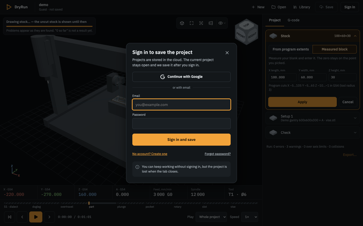
Figure 0c. Save as a guest of the online version.
- New account: No account? Create one switches the dialog to
Create an account: type your email and a password (at least 10 characters, with a lowercase letter and a digit) and press Create account (Create account and save after Save): you get an email with a code; the dialog asks for it (Enter the code from the email), and Confirm and sign in (or Confirm and save) creates the account and continues. Send the code again if it does not arrive (check the spam folder). Sign in and Create account are separate (task066): Sign in never creates an account — a wrong password, or an email without an account, readsWrong email or password.(the service does not say which); Create account with an email that has an account readsAn account with this email already exists. Sign in, or reset the password.An account whose code was never entered asks for the code again at the next sign-in. - Forgot password? asks for your email and sends a code; enter the code and a new password, and you are signed in.
- Continue with Google (task049; first in the dialog, above
or with email, shown only once the site has Google sign-in set up) opens a small Google window: choose your Google account, and the window closes by itself; the dialog closes and what you were doing goes on, exactly as after a password sign-in (the page is not reloaded, unsaved changes stay). If Chrome blocks the window, the whole tab goes to Google instead and comes back: the project on screen is kept in this browser first and opened again on the return, then saved (or My projects opens). A Google account with the same email as an account you created with a password is the same account (same projects): the very first time, the dialog may sayYour Google account is now linked to your DryRun account. Click Continue with Google again.— click it once more. DryRun receives only your email and name from Google. Sign out after a Google sign-in also signs you out of DryRun's Google sign-in in a small window that closes by itself, so the next Continue with Google asks which account to use (you stay signed in to Google itself).
What is stored where. Signed in, Save sends the project (the same files Export… would write, packed as one zip) to DryRun's server on AWS (Frankfurt, eu-central-1): the files in a private storage bucket, the My projects row (name, machine, program count, setup, last check) in a database, both under your account only. A save first uploads the files and only then switches My projects to them, so a failed save leaves the previous version as it was. Your password is never stored by DryRun (the sign-in is done with Amazon Cognito); the browser keeps a sign-in token for this site so that a reload keeps you signed in; Sign out removes it. If the server cannot be reached the save says No connection; the project stays open and the project stays Not saved (and kept as the draft, below): press Save again later, or Export… it. When the server is busy (more than about 20 requests a second) it says DryRun's server is busy; wait a few seconds and try again. A project whose zip is over 100 MB is not sent: The project is larger than 100 MB; remove unused meshes.
Sign out (user menu) keeps what is open on screen, as a guest's unsaved project (task066): the header reads Guest · not saved and the project is kept as the draft; the next Save asks you to sign in and saves it (into the same project if you sign in to the same account). The Projects window locks again.
The guest's draft (task066). Without an account nothing is lost when the tab closes: the project on screen, with its unsaved changes, is kept in this browser as a draft about a second after each change. On the next visit the Projects window shows You have an unsaved draft from 10:42 with Restore (the project as it was, still not saved) and Discard; sign in from Save to store it in your account, which also clears the draft. Don't save (when leaving it) clears it too. The draft is in this browser only (clearing the site's data removes it). The user menu's Projects opens the Projects window, and Delete there says The project is removed from your account.
Projects from this browser. If this browser has projects, machines or Library fixtures from the local version of the same site, the first sign-in asks Upload 3 projects, 1 machine and 2 fixtures from this browser to your account?: Upload copies them into the account (toast Uploaded … to your account; the copies in the browser stay), Not now asks again at the next sign-in, Don't ask again stops asking.